Lesson 4: Biomass Pyrolysis and Pretreatment
Lesson 4: Biomass Pyrolysis and PretreatmentLesson 4: Biomass Pyrolysis and Pretreatment Overview
This week’s lesson continues with thermal processes for biomass conversion, this time concentrating on pyrolysis; pyrolysis is heating material in an inert environment. In addition to providing an in-depth explanation of this process, this lesson will also discuss the various chemical structures found in biomass (essentially in lignocellulosic biomass) and pretreatments that are done to make the materials more amenable for fuel production.
Lesson Objectives
By the end of this lesson, you should be able to:
- explain how pyrolysis is different from gasification and combustion;
- explain how the products are made and used as fuels and chemicals;
- determine which thermal process is best to use depending on biomass source and product utilization;
- describe the basic chemical structures of biomass, namely lignocellulosic biomass;
- evaluate pretreatment options for lignocellulosic options and explain why they are necessary.
Lesson 4 Road Map
This lesson will take us one week to complete. Please refer to the Course Syllabus for specific time frames and assignment due dates.
Questions?
If there is anything in the lesson materials that you would like to comment on or don't quite understand, please post your thoughts and/or questions to our Throughout the Course Questions and Comments discussion forum. The discussion forum will be checked regularly. While you are there, feel free to post responses to your classmates if you are able to help. Regular office hours will be held to provide help for EGEE 439 students.
4.1 Biomass Pyrolysis
4.1 Biomass PyrolysisdifferencesThe figure below shows a graphic of the four methods of thermochemical conversion of biomass, with pyrolysis highlighted. We just went over combustion and gasification, and we’ll cover direct liquefaction later on in the semester.
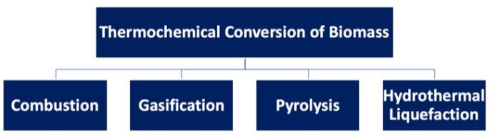
There are differences in each of the thermal processes. For combustion, the material is in an oxygen-rich atmosphere, at a very high operating temperature, with heat as the targeted output. Gasification takes place in an oxygen-lean atmosphere, with a high operating temperature and gaseous products being the main target (syngas production in most cases). Direct liquefaction (particularly hydrothermal processing) occurs in a non-oxidative atmosphere, where biomass is fed into a unit as an aqueous slurry at lower temperatures, and bio-crude in liquid form is the product.
So, what is pyrolysis? There are several definitions depending on the source, but essentially, it is a thermochemical process, conducted at 400-600°C in the absence of oxygen. The process produces gases, bio-oil, and a char, and as noted in Lesson 4, is one of the first steps in gasification or combustion. The composition of the primary products made will depend on the temperature, pressure, and heating rate of the process.
There are advantages, both economic and environmental, to doing pyrolysis. They are:
- utilization of renewable resources through a carbon-neutral differences route – environmental potential;
- utilization of waste materials such as lumber processing waste (barks, sawdust, forest thinnings, etc.), agricultural residues (straws, manure, etc.) – economic potential;
- self-sustaining energy – economic potential;
- conversion of low energy in biomass into high energy density liquid fuels – environmental & economic potentials;
- potential to produce chemicals from bio-based resources – environmental & economic potentials.
Pyrolysis was initially utilized to produce charcoal. In indigenous cultures in South America, the material was ignited and then covered with soil to reduce the oxygen available to the material – it left a high carbon material that could stabilize and enrich the soil to add nutrients ([Discussion of applications of pyrolysis], (n.d.), Retrieved from MagnumGroup.org). It has also been used as a lighter and less volatile source of heat for cooking (i.e., “charcoal” grills) in countries where electricity is not widely available and people use fuel such as this to cook with or heat their homes (Schobert, H.H., Energy, and Society: An Introduction, 2002, Taylor & Francis: New York). Not only is there a solid product, such as charcoal, but liquid products can also be produced depending on the starting material and conditions used. Historically, methanol was produced from the pyrolysis of wood.
This process for pyrolysis can also be called torrefaction. Torrefaction is typically done at relatively low pyrolysis temperatures (200-300°C) in the absence of oxygen. The feed material is heated up slowly, at less than 50°C/min, and is done over a period of hours to days – this way the volatiles are released and carbon maintains a rigid structure. In the first stage, water, which is a component that can inhibit the calorific value of a fuel, is lost. This is followed by a loss of CO, CO2, H2, and CH4 in low quantities. By doing this, approximately 70% of the mass is retained with 90% of the energy content. The solid material is hydrophobic (with little attraction to water) and can be stored for a long period of time.
Classification of pyrolysis methods
There are three types of pyrolysis: 1) conventional/slow pyrolysis, 2) fast pyrolysis, and 3) ultra-fast/flash pyrolysis. The table and figure below summarize how each method differs in temperature, residence time, heating rate, and products made.
As mentioned earlier, slow pyrolysis is typically used to modify the solid material, minimizing the oil produced. Fast pyrolysis and ultra-fast (flash) pyrolysis maximize the gases and oil produced.
Fast pyrolysis is a rapid thermal decomposition of carbonaceous materials in the absence of oxygen at moderate to high heating rates. It is the most common of the methods, both in research and in practical use. The major product is bio-oil. Pyrolysis is an endothermic process. Along with the information listed in the table, the feedstock must be dry; of smaller particles (< 3 mm); and typically done at atmospheric temperature with rapid quenching of the products. The yields of the products are: liquid condensates – 30-60%; gases (CO, H2, CH4, CO2, and light hydrocarbons) – 15-35%; and char – 10-15%.
Ultra-fast, or flash, pyrolysis is an extremely rapid thermal decomposition, with a high heating rate. The main products are gases and bio-oil. Heating rates can vary from 100 to 10,000° C/s, and residence times are short in duration. The yields of the products are: liquid condensate ~10 - 20%; gases – 60 - 80%; and char – 10 - 15%.

Accessible version of Classification of pyrolysis methods with differences in temperature, residence time, heating rate, and major products.
| Method | Temperature (°C) | Residence Time | Heating rate (°C/s) | Major products |
|---|---|---|---|---|
| Conventional/slow pyrolysis | Med-high 400-500 | Long 5-30 min | Low 10 | Gases Char Bio-oil (tar) |
| Fast pyrolysis | Med-high 400-650 | Short 0.5-2 s | High 100 | Bio-oil (thinner) Gases Char |
| Ultra-fast/flash pyrolysis | High 700-1000 | Very short < 0.5 s | Very high >500 | Gases Bio-oil |

Figure summarizing different pyrolysis conditions and the effect on product distribution.
| Heating rate | Time | Temperature (ºC) | Char | Liquid | Gas |
|---|---|---|---|---|---|
| Slow (<103 W/m2) | 1000s | ~500ºC | 25% | 35% | 40% |
| Medium (>104 W/m2) | 100s | ~500ºC | 17% | 58% | 35% |
| Fast (>105 W/m2) | 1s | ~500ºC | 15% | 65% | 20% |
| Flash (>106 W/m2) | 0.01s | ~500ºC | 10% | 70% | 20% |
| Slow (<103 W/m2) | 1000s | ~1000ºC | 40% | 35% | 25% |
| Medium (>104 W/m2) | 100s | ~1000ºC | 20% | 37% | 43% |
| Fast (>105 W/m2) | 1s | ~1000ºC | 15% | 20% | 65% |
| Flash (>106 W/m2) | 0.01s | ~1000ºC | 0% | 15% | 95% |
Bio-oil Product Properties
Crude bio-oils are different from petroleum crude oils. Both can be dark and tarry with an odor, but crude bio-oils are not miscible with petro-oils. Bio-oils have high water content (20-30%); their density is heavier than water (1.10-1.25 g/mL); their heating value is ~5600-7700 Btu/lb (13-18 MJ/kg). Bio-oils have high oxygen content (35-50%), which causes high acidity (pH as low as ~2). Bio-oils are also viscous (20-1000 cp @ 40°C) and have high solid residues (up to 40%). These oils are also oxidatively unstable, so the oils can polymerize, agglomerate, or have oxidative reactions occurring in situ which lead to increased viscosity and volatility. The values in the table below compare the properties of bio-oil to petroleum-based heavy fuel oil.
| Physical Property | Bio-oil | Heavy fuel oil |
|---|---|---|
| Moisture Content | 15-30 | 0.1 |
| pH | 2.5 | -- |
| Specific gravity | 1.2 | 0.94 |
| Elemental composition (wt%) | - | - |
| C | 54-58 | 85 |
| H | 5.5-7.0 | 11 |
| O | 35-40 | 1.0 |
| N | 0-0.2 | 0.3 |
| Ash | 0-0.2 | 0.1 |
| HHV, MJ/kg | 16-19 | 40 |
| Viscosity (cp, @50°C) | 40-100 | 180 |
| Solids (wt %) | 0.2-1 | 1 |
| Distillation residue (wt%) | Up to 50 | 1 |
Process Considerations
Several components are necessary for any pyrolysis unit, outside of the pyrolyzer itself. The units and how they are connected are shown in the figure below.

The goal of the process is to produce bio-oil from the pyrolyzer. The bio-oil that’s generated has potential as a transportation fuel after upgrading and fractionation. Some can be used for making specialty chemicals as well, especially ring-structure compounds that could be used for adhesives. The gases that are produced contain combustible components, so the gases are used to generate heat. A biochar is produced as well. Biochar can be used as a soil amendment that improves the quality of the soil, sequesters carbon, or can even be used as a carbon material as a catalyst support or activated carbon. There will also be a mineral-based material called ash once it’s been processed. Typically, the ash must be contained.
The next units to be considered are separation units. Char is solid, so it is typically separated using a cyclone or baghouse. It can be used as a catalyst for further decomposition into gases because the mineral inherent in the char as well as the carbon can catalyze the gasification reactions. The liquids and gases must also be separated. Usually, the liquids and gases must be cooled in order to separate the condensable liquids from the non-condensable gases. The liquids are then fractionated and will most likely be treated further to improve the stability of the liquids. At times, the liquid portion may plug due to heavier components. The non-condensable gases need to be cleaned of any trace amounts of liquids and can be reused if needed.
The next consideration is the heat sources for the unit. Hot flue gas is used to dry the feed. As the flue gas contains combustible gases, they can be partially combusted to provide heat. Any char that is left over is burned as a major supply of heat. And, biomass can be partially burned as another major source of heat.
Another important process to consider is the means of heat transfer. Much of it is indirect, through metal walls and tube and shell units. Direct heat transfer has to do with char and biomass burning. In the fluidized bed unit, the carrier (most often sand) brings in the heat, as the carrier is heated externally and recycled to provide heat to the pyrolyzer.
Types of Pyrolyzers
So, what types of pyrolyzers are used? The more common types are fluidized-bed pyrolyzers. The figures below show schematics of two different types. The advantages of using fluid beds are uniform temperature and good heat transfer; high bio-oil yield of up to 75%; a medium level of complexity in construction and operation; and ease of scaling up. The disadvantages of fluid beds are the requirement for small particle sizes; a large quantity of inert gases; and high operating costs. The circulating fluid bed pyrolyzer, (CFB), shown below, has similar advantages, although medium-sized particle sizes for feed are used. Disadvantages include a large quantity of heat carriers (i.e., sand); more complex operation, and high operating costs.
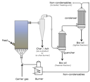
Fluid-bed with electrostatic precipitator.
Schematic of a fluid bed with electrostatic precipitator. The carrier gas enters the fluid bed that has an intake feed. The gas then goes through a cyclone and the char and ash are removed as a product or taken to the char burner. The gas then passes through the quencher and the heavier fraction is removed as bio-oil, it then passes to the condenser where the lighter fraction is condensed as bio-oil and the non-condensable are taken to the boiler or the burner. Any gases created at the burner are used as carrier gas.
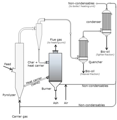
Fluidized bed with circulating heat carrier (circulating fluid-bed (CFB) pyrolyzers).
Schematic of a fluid-bed with circulating heat carrier (circulating fluid-bed (CFB) pyrolyzers. The carrier gas enters the bottom of the fluid bed through a pyrolyzer. The fluid bed also has an intake feed halfway up. The gas then goes through a cyclone and the char and heat carriers are removed and taken to a burner. The heat carriers (sand) are returned to the fluid bed/pyrolyzer. The ash is removed and flue gas is taken to the heating unit. The gases that come out of the cyclone then pass through the quencher and the heavier fraction is removed as bio-oil, it is then passed to the condenser where the lighter fraction is condensed as bio-oil, and the non-condensable is taken to the boiler or the burner. Any gases created at the burner are used as carrier gas.
Two other types of pyrolyzers are the Rotating Cone and the Auger pyrolyzers. The rotating cone creates a swirling movement of particles through a g-force. This type of pyrolyzer is compact, has a relatively simple construction and operation, and has a low heat carrier/sand requirement. However, it has a limited capacity, requires feed to be fine particles, and is difficult to scale up. Auger pyrolyzers are also compact, simple in construction, and easy to operate; they function at a lower process temperature as well (400 °C). The disadvantages of Auger pyrolyzers include long residence times, lower bio-oil yields, high char yield, and limits in scaling up due to heat transfer limits.

Rotating cone pyrolyzer.
Schematic of a rotating cone pyrolyzer. The cone has feed at the bottom and heat is applied to the outside walls of the cone. A motor spins the cone and the gas/condensables come out the top as does the char/ash.
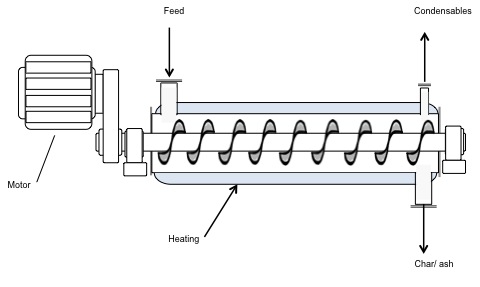
Auger pyrolyzer.
Schematic of an Auger pyrolyzer. The diagram looks like a cylinder with a corkscrew inside. A motor is attached to the rotating corkscrew. The walls of the cylinder are heated and at one end there is a feed. On the other end, there are outtake ports for condensables to come out the tops and char/ash to come out the bottom.
Bio-Oil Upgrading
As noted earlier, bio-oil has issues and must be upgraded, which means essentially processed to remove the problems. These problems include high acid content (which is corrosive), high water content, and high instability both oxidatively and thermally (which can cause unwanted solids formation).
The oils must be treated physically and chemically. Physical treatments include the removal of char via filtration and emulsification of hydrocarbons for stability. Bio-oils are also fractionated, but not before chemical treatments are done. The chemical treatments include esterification (a reaction with alcohol to form esters – this will be covered in detail when discussing biodiesel production); catalytic de-oxygenation/hydrogenation to remove oxygen and double bonds; thermal cracking for more volatile components; physical extraction; and syngas production/gasification.
Catalytic de-oxygenation/hydrogenation takes place. A catalyst is used along with hydrogen gas; specialty catalysts are used, such as sulfides and oxides of nickel, cobalt, and molybdenum. Hydrogenation is commonly used in petroleum refining for the removal of sulfur and nitrogen from crude oil and to hydrogenate the products where double bonds may have formed in processing. Catalytic processes are separate processes and use specific equipment to perform the upgrading. One problem can be that there may be components of bio-oil that may be toxic to catalysts.
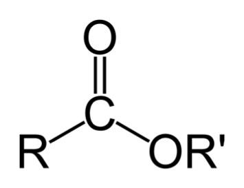
Esterification reacts to the corrosive acids in bio-oils with alcohol to form esters. An ester is shown below. A discussion of the esterification reaction will be discussed in the biodiesel lesson.
Bio-oil can also be thermally cracked and/or made into syngas through gasification. Please refer to Lesson 2 for the thermal cracking discussion and Lesson 4 for the gasification discussion. One other process that can be utilized is physical extraction, although extraction takes place due to the affinity of some of the compounds to a particular fluid. One example is the extraction of phenols. Phenols can be extracted using a sodium solution such as sodium hydroxide in water; the phenolic compounds are attracted to the sodium solution, while the less oxygenated compounds will stay in the organic solution. Again, this will be discussed in more detail in later lessons. The figure below shows a schematic of a typical processing unit to upgrade bio-oil.
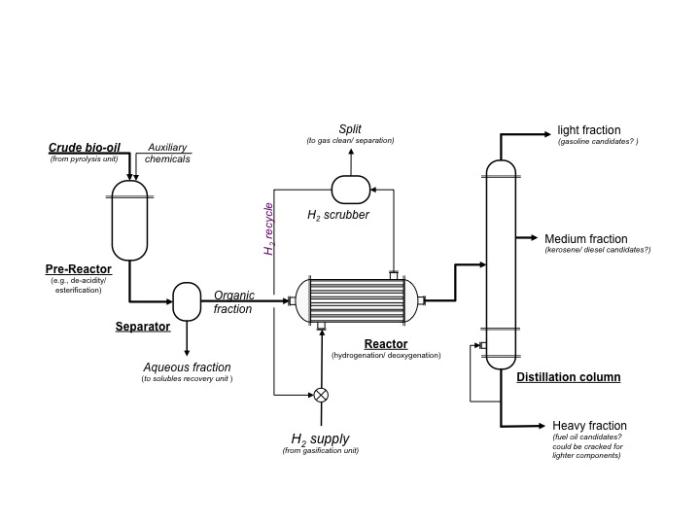
Schematic of a typical processing unit to upgrade bio-oil.
Schematic of a typical processing unit to upgrade bio-oil. Crude bio-oil and auxiliary chemicals ender the pre-reactor which does things such as de-acidify or esterify. From the pre-reactor, the crude bio-oil goes to the separator. The aqueous fraction is removed and goes to the solubles recovery unit. The organic fraction goes to the reactor where hydrogen gas is pumped in to do hydrogenation and deoxygenation. The gases are removed to a hydrogen scrubber which cleans and separates the gases. The hydrogen gas is recycled. The bio-oil then goes to a distillation column. The heavy fraction is a fuel oil candidate and could be cracked for lighter components. The medium fraction can become kerosene or a diesel candidate. The lightest fraction can become a gasoline candidate.
Biomass Pretreatment
Current methods of generating biofuels are primarily from starch or grain, and starch hydrolysis is fairly straightforward. However, because the starch feedstocks are typically food-based, the goal is to develop technologies to produce ethanol from cellulose; cellulose is obtained from lignocellulosic biomass sources and must be pretreated before breaking down into ethanol. Below is a schematic of the differences in processing for starch (current) and cellulose (emerging). Before we go any further, we will have a short tutorial on the various components of lignocellulosic biomass.
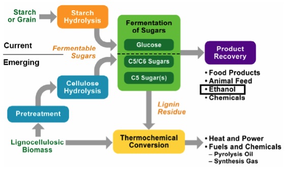
Schematic of processing differences for cellulose and starch.
Schematic of processing differences for cellulose and starch. For starch or grain, it goes through starch hydrolysis and then the fermentation of glucose to recover the final product. The final products are food products, animal feed, ethanol, and chemicals.
For cellulose (lignocellulosic biomass) it must go through a pretreatment before entering cellulose hydrolysis and then the fermentation of carbon 5 and 6 sugars to recover the final products. The final products are food products, animal feed, ethanol, and chemicals. Any lignin residue goes through thermochemical conversion to become heat and power, and fuels and chemicals: pyrolysis oil and synthesis gas.
4.2 Biomass Carbohydrate Tutorial
4.2 Biomass Carbohydrate TutorialWhen the word carbohydrate is used, I typically think of the carbohydrates in food. Carbohydrates are the sugars and complex units composed of sugars. This section will describe each.
Sugars are also called saccharides. Monomer units are single units of sugars called monosaccharides. Dimer units are double units of sugars called disaccharides. Polymers contain multiple units of monomers and dimers and are called polysaccharides.
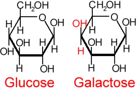
So, what are typical monosaccharides? They are made up of a molecule that is in a ring structure with carbons and oxygen. The first figure below shows the structure of glucose; it is made up of C6H12O6. Glucose is distinguished by its structure: five carbons in the ring with one oxygen; CH2OH attached to a carbon; and OH and H groups attached to the other carbons. This sugar is known as blood sugar and is an immediate source of energy for cellular respiration. The second figure shows galactose next to glucose, and we can see that galactose is almost like glucose, except on the No. 4 carbon the OH and H are an isomer and just slightly different (highlighted in red on the galactose molecule). Galactose is a sugar monomer in milk and yogurt. The third figure shows fructose; while it still has a similar chemical formula as glucose (C6H12O5), it is a five-membered ring with carbons and oxygens, but two CH2OH groups. This is a sugar found in honey and fruits.


We also have disaccharides as sugars in food. Disaccharides are dimers of the monomers we just discussed and are shown below. One of the most common disaccharides is sucrose, which is a common table sugar and is shown in the figure below. It is a dimer of glucose and fructose. Another common sugar dimer is lactose. It is the major sugar in milk and a dimer of galactose and glucose. Maltose is also a sugar dimer but is a product of starch digestion. It is a dimer made up of glucose and glucose. In the next section, we will discuss what starch and cellulose are composed of in order to see why maltose is a product of starch digestion.


Carbohydrate structure
All carbohydrate polymers are monomers that connect with what is called a glycosidic bond. For example, sucrose is a dimer of glucose and fructose. In order for the bond to form, there is a loss of H and OH. So, another way to show this is:
C12H22O11 = 2 C6H12O6 − H2O
And as dimers can form, polymers will form and are called polysaccharides. Typical polysaccharides include 1) glycogen, 2) starch, and 3) cellulose. Glycogen is a molecule in which animals store glucose by polymerizing glucose, as shown below.

Starches are similar to glycogen, with a slightly different structure. Starch is composed of two polymeric molecules, amylose and amylopectin. The structures of both are shown below.

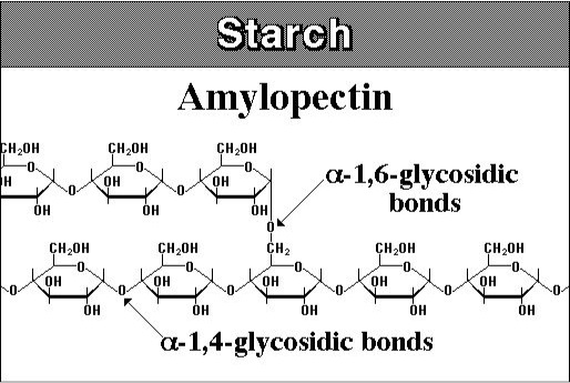
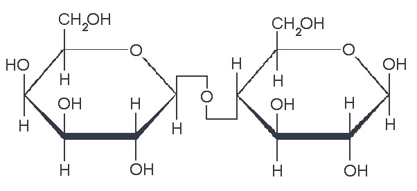
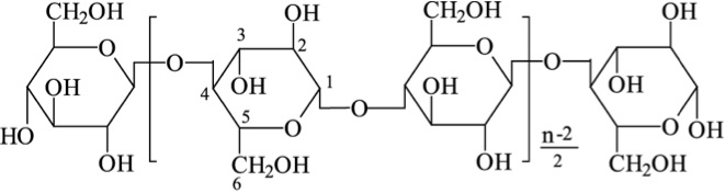
About 20% of starch is made up of amylose and is a straight chain that forms into a helical shape with α-1,4 glycosidic bonds and the rest of the starch is amylopectin, which is branched with α-1,4, and α-1,6 glycosidic bonds. The figure below shows the structure of cellulose. Cellulose is a major molecule in the plant world; it is also the single most abundant molecule in the biosphere. It is a polymer of glucose and has connectors of the glucose molecule that are different from starch; the linkages are β-1,4 glycosidic bonds. The polymer of cellulose is such that it can form tight hydrogen bonds with oxygen, so it is more rigid and crystalline than starch molecules. The rigidity makes it difficult to break down.
4.3 Pretreatment of Lignocellulosic Biomass
4.3 Pretreatment of Lignocellulosic BiomassWhen the word carbohydrate is used, I typically think of the carbohydrates in food. Carbohydrates are the sugars and complex units composed of sugars. This section will describe each.
Sugars are also called saccharides. Monomer units are single units of sugars called monosaccharides. Dimer units are double units of sugars called disaccharides. Polymers contain multiple units of monomers and dimers and are called polysaccharides.
So, what are typical monosaccharides? They are made up of a molecule that is in a ring structure with carbons and oxygen. The first figure below shows the structure of glucose; it is made up of C6H12O6. Glucose is distinguished by its structure: five carbons in the ring with one oxygen; CH2OH attached to a carbon; and OH and H groups attached to the other carbons. This sugar is known as blood sugar and is an immediate source of energy for cellular respiration. The second figure shows galactose next to glucose, and we can see that galactose is almost like glucose, except on the No. 4 carbon the OH and H are an isomer and just slightly different (highlighted in red on the galactose molecule). Galactose is a sugar monomer in milk and yogurt. The third figure shows fructose; while it still has a similar chemical formula as glucose (C6H12O5), it is a five-membered ring with carbons and oxygens, but two CH2OH groups. This is a sugar found in honey and fruits.
We also have disaccharides as sugars in food. Disaccharides are dimers of the monomers we just discussed and are shown below. One of the most common disaccharides is sucrose, which is a common table sugar. It is a dimer of glucose and fructose. Another common sugar dimer is lactose. It is the major sugar in milk and a dimer of galactose and glucose. Maltose is also a sugar dimer, but is a product of starch digestion. It is a dimer made up of glucose and glucose. In the next section, we will discuss what starch and cellulose are composed of in order to see why maltose is a product of starch digestion.
Carbohydrate structure
All carbohydrate polymers are monomers that connect with what is called a glycosidic bond. For example, sucrose is a dimer of glucose and fructose. In order for the bond to form, there is a loss of H and OH. So, another way to show this is:
There is a wide variety of sources for lignocellulosic biomass, which includes agricultural waste (i.e., corn stover), forest waste from furniture and home construction, municipal solid waste, and energy crops. They all look very different, but all are composed of cellulose, hemicellulose, lignin, and other minor compounds. The figure below shows switchgrass (with parts magnified to emphasize different parts of the plant structure). Once you get down to the microfibril structure, you can see the components of the microfibril, which include lignin on the outside layer, hemicellulose on the next layer, and finally, cellulose. Because of the structure, the lignocellulose is difficult to break down, which is known as recalcitrance. In order to get to the cellulose, the cell wall has to be opened up, the lignin has to be removed or separated from the hemicellulose and cellulose, and then the cellulose, crystalline in nature, has to be broken down. All these steps are resistant to microbial attack, so pretreatment methods are used to break it apart. In other words, biomass recalcitrance requires pretreatment.

The image is a scientific diagram illustrating the structure and composition of cellulose in plant cells. It begins with a depiction of plant cells, highlighting the cell wall, which is the primary location of cellulose.
A magnified section of the cell wall reveals a layered mesh of microfibrils, which are bundles of cellulose chains. These microfibrils are shown in greater detail, illustrating how they are composed of tightly packed cellulose molecules.
The diagram further breaks down the cellulose molecule into its basic building blocks, showing repeating units of glucose and cellobiose. It also includes a representation of crystalline cellulose, where the cellulose chains are aligned in a highly ordered structure, contributing to the strength and rigidity of the plant cell wall.
Overall, the image provides a clear and detailed view of how cellulose is organized from the molecular level up to its role in the plant cell wall, emphasizing its structural importance in plant biology.
Another Perspective
You can access the following online journal article to see another illustration of lignocellulose but with the lignin component included (Figure 1):
Pretreatment is the most costly step; however, the only process step more expensive than pretreatment is no pretreatment. Without pretreatment, yields are low and drive up all other costs, more than the amount saved without pretreatment. Increased yields with pretreatment reduces all other unit costs. Below is a schematic of the role pretreatment plays. Pretreatment, depending on the method, will separate the lignin, the hemicellulose, and the cellulose. The schematic shows how these break apart. Part of the lignin and the hemicellulose are dissolved in liquid during hydrolysis, and part of the lignin and the cellulose are left as a solid residue. There is a partial breakdown of the polymeric molecules, and the cellulose is now more accessible to microbial attack.

Pretreatment is costly and affects both upstream and downstream processes. On the upstream side, it can affect how the biomass is collected or harvested, as well as the comminution of the biomass. Downstream of pretreatment, the enzyme production can be affected, which in turn will affect the enzymatic hydrolysis and sugar fermentation. Pretreatment can also affect hydrolyzate conditioning and hydrolyzate fermentation. The products made and the eventual final processing also will be affected by pretreatment. However, it is more costly to not do pretreatment.
There are two different types of pretreatment. Physical effects disrupt the higher-order structure and increase surface area and chemical/enzyme penetration into plant cell walls, including mechanical size reduction and fiber liberation. Chemical effects include solubilization, depolymerization, and breaking of crosslinks between macromolecules. The individual components can “swell," depending on the organic solvent or acid used. Lignin can be “redistributed” into a solution, and lignin and carbohydrates can be depolymerized or modified chemically.
The following pretreatment technologies will be discussed in more depth: 1) size reduction, 2) low pH method, 3) neutral pH method, 4) high pH method, 5) organic solvent separation, 6) ionic liquid separation, and 7) biological treatments.
4.3a Size Reduction
4.3a Size ReductionSize reduction is also known as comminution. Decreasing particle size of biomass improves accessibility to plant cell wall carbohydrates for chemical and biochemical depolymerization. It can also increase the bulk density for storage and transportation. There is a cost of energy when using mechanical size reduction. For example, 20-40 kWh/metric tons are needed to reduce the size of hardwood chips to coarse particles of 0.6-2.0 mm in size, and kWhs typically have a cost of anywhere from $0.04-0.10 per kWh. To reduce the size of particles to a fine size (0.15-0.30 mm), 100-200 kWh/ton is required.
There are multiple methods used to reduce the size of particles, and the method used will depend on whether the sample is dry or wet. There are hammer mills (a repetitive hammering of the sample), knife mills (a rotating knife slices the sample), and ball mills (the sample is put into a container with metal balls and rolled). Sometimes the sample has to be shredded and dried before using some of these techniques.
Samples can also be “densified.” Samples can be mixed with some sort of binder (to keep the materials together, like glue) and pushed into shape, or pelletized. This increases the bulk density (i.e., from 80-150 kg/m3 for straw or 200 kg/m3 for sawdust to 600-700 kg/m3 after densification). This can lower transportation costs, reduce the storage volume, and make handling easier. After densification, the materials usually have lower moisture content.

4.3b Low pH Methods
4.3b Low pH MethodsThe mechanism for low pH treatments is the hydrolysis of hemicellulose. Hydrolysis is a reaction with water, where acid is added to the water to accelerate the reaction time. Several acids can be used, including dilute sulfuric acid (H2SO4), gaseous sulfur dioxide (SO2), hydrochloric acid (HCl), phosphoric acid (H3PO4), and oxalic acid (C2H2O4). Because it is a reaction, the key parameters affecting it include temperature, time, acid concentration, and moisture content of the biomass. The following reactions can take place: hemicellulose can be solubilized, lignin can be separated, acetyl groups are removed, and the surface of the biomass becomes more accessible. As an example, the α-1,4 bond is broken by the water and acid to yield two glucose units. An enzyme, amylase, can also promote the reaction. The addition of acid and elevated temperature increases the rate of reaction.

Not only is acid used to facilitate hydrolysis, but acid-catalyzed dehydration of sugars can form furans, which can break down into organic acids such as formic acid and levulinic acid. These compounds can be toxic to the enzymes that are used in sugar fermentation. So after the reaction, the residual acid must be neutralized, and inhibitors formed or released during pretreatment must be reduced. Two methods are to use calcium oxide (also known as overliming) or ammonium hydroxide.
Calcium oxide is cheap, forms gypsum during the process, and has a loss of sugar of ~10%, with the necessity of by-product removal and disposal. The reaction is shown below in Reaction 1.
The advantage of using ammonium hydroxide is that less sugar is lost and less waste is generated, but the cost is higher. The reaction is shown below in Reaction 2.
The figures below show process diagrams of typical configurations and reaction conditions for sulfuric acid and SO2.

Schematic of sulfuric acid pretreatment process.*
Schematic of sulfuric acid pretreatment process. Biomass is added to dilute sulfuric acid, called acid impregnation (0.5 – 5.0% H2SO4) it then goes to dilute acid pretreatment around (140-200 C). This pretreatment can take seconds to hours. It then becomes a slurry which goes into neutralization conditioning. The solids go to enzymatic hydrolysis where hexose sugars and solid residue (lignin) are separated. The liquids from the neutralization condition go to acid post-hydrolysis. The slurry can also go to solid/liquid separation. The solid products of this separation go to neutralization condition and the liquids go to acid post-hydrolysis. Acid post-hydrolysis yields pentose sugars.

Schematic of sulfur dioxide pretreatment process.*
Schematic of sulfur dioxide pretreatment process. Biomass with water undergoes biomass humidification (50%-70% M.C.) and then it undergoes SO2 impregnation (1-5%) and finally a steam explosion (180-210 C). This pretreatment can take seconds to minutes. It then becomes a slurry which goes into neutralization conditioning. The solids go to enzymatic hydrolysis where hexose sugars and solid residue are separated. The liquids from the neutralization conditioning go-to acid post-hydrolysis. The slurry can also go to solid/liquid separation. The solid products of this separation go to neutralization conditioning and the liquids go to acid post-hydrolysis. Acid post-hydrolysis yields pentose sugars.
4.3c Neutral pH Pretreatment
4.3c Neutral pH PretreatmentPretreatment can also take place in neutral pH water. There are two pathways that can occur. One is when acidic compounds are released from acetylated hemicellulose, mainly acetic acid. This is also called autohydrolysis. Water can also dissociate as the temperature and pressure increase to near the supercritical point (approximately 374°C, 3200 psi), into H+ and OH−, and as this happens, the water behaves like an acid/base system. It is done in water without added chemicals, either in liquid hot water, steam explosion, or water near the supercritical point. The key parameters are time, temperature, and moisture content, and the effects are similar to low pH methods. A schematic for liquid hot water processing is shown in the figure below.
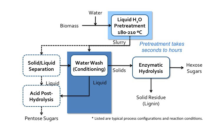
Liquid hot water process flow diagram*.
Schematic of liquid hot water processes flow diagram. Biomass is added to water and sent to liquid H2O pretreatment (180-210 C). Pretreatment can take seconds to hours. It then becomes a slurry which goes into water wash conditioning. The solids go to enzymatic hydrolysis where hexose sugars and solid residue (lignin) is separated. The liquids from the water wash conditioning go to acid post-hydrolysis. The slurry can also go to solid/liquid separation. The solid products of this separation go to water wash conditioning and the liquids go to acid post-hydrolysis. Acid post-hydrolysis yields pentose sugars.
One process, developed by Inbicon, is a counter-current multi-stage hot water pretreatment process. There is a pilot-scale unit at Skærbæk, Denmark. It is a three-stage process using hot water (hydrothermal) at 80°C, 160-200 °C, and 190-230°C. After the first stage, a liquid composed of C5 molasses (sugar) is taken out of the process, which is used for animal feed. After the third stage, the fiber fraction contains cellulose and lignin. Bioethanol and solid fuel for heat and power are produced when using enzymes, yeast, and fermentation. The figure below shows the before and after pretreatment of wheat straw (the raw wheat straw and the cellulosic-lignin portion).

The next pretreatment processes to discuss are at high pH. The high pH removes the lignin portion of biomass through the breaking of ether linkages (R-O-R’) that hold aromatic phenolic compounds together; ring opening can also take place. It is a depolymerization process. There are several processes and bases used, including lime, calcium carbonate, potassium hydroxide, sodium hydroxide, and aqueous ammonia. Key parameters include temperature, reaction time, concentration of base, moisture of the feed material, as well as oxidizing agents. The effects include the removal of most of the lignin, some removal of hemicellulose, and the removal of acetyl links between lignin and hemicellulose.
Lignin is most prominent in grasses and woody biomass. It composes 6-35% of lignocellulosic biomass, depending on the type of grass or wood. Lignin is comprised of crosslinked, branched, monoaromatic units with methoxy and propyl alcohol functional groups. These are shown in the first figure below. The second figure below shows a model of a lignin molecule and how the aromatic monomers are linked together.


4.3d High pH (Alkaline) Pretreatment
4.3d High pH (Alkaline) PretreatmentThere are two possible outcomes for the chemistry behind the high pH treatment: 1) one is essentially a degradation reaction that liberates lignin fragments and leads to lignin dissolution, and 2) the other is condensation reactions that increase the molecular size of lignin fragments and result in lignin precipitation. As you can see, lignin is a complicated molecule, with a variety of linkages, so reactions are complicated due to lignin complexity. The addition of oxidizing agents greatly improves delignification.
There are multiple processes that have been developed for this type of treatment. The first figure below shows the lime pretreatment process flow diagram. The pretreatment can be done under various conditions, such as oxidative and non-oxidative conditions, short-term high temperature (100-200°C, 1-6 h), and long-term low temperature (25-65°C, 1-8 weeks). The second figure below shows the soaking in aqueous ammonia (SAA) process flow diagram.
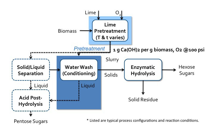
Lime pretreatment process flow diagram*.
Biomass enters a lime pretreatment with lime and oxygen gas. The temperatures and time of this process vary. The is about 1g of Ca(OH)2 per 1g of biomass the oxygen gas is at 100psi. After pretreatment, the biomass becomes a slurry that goes into water wash conditioning. The solids go to enzymatic hydrolysis where hexose sugars and solid residue (lignin) are separated. The liquids from the water wash conditioning go-to acid post-hydrolysis. The slurry can also go to solid/liquid separation. The solid products of this separation go to water wash conditioning and the liquids go to acid post-hydrolysis. Acid post-hydrolysis yields pentose sugars.

Soaking in aqueous ammonia (SAA) process flow diagram*.
Biomass is soaked in aqueous ammonia at 120-180 C. This pretreatment can take minutes to hours. The biomass then goes to post-washing with water and counter-current leaching. The solids go to enzymatic hydrolysis where hexose sugars and the solid residue are separated. The liquids go-to acid post-hydrolysis which removes the pentose sugars and lignin. This also removes the dilute. NH3 which is recycled.
One of the more developed high-pH processes is the ammonia fiber expansion (AFEX) process. Lignocellulosic biomass is soaked in liquid ammonia (causing swelling) followed by the rapid release of pressure (causing expansion). Anhydrous liquid ammonia is used, and key parameters include temperature, residence time, ammonia concentration, and moisture content of the biomass. During this process, there is virtually no compositional change, but lignin is relocated, cellulose is decrystallized, and hemicellulose is depolymerized. This method increases the size and number of micropores in the cell wall to allow for greater accessibility of chemicals for the following stages of processing. A process schematic is shown below.

AFEX process flow diagram*.
Biomass is added with ammonia to AFEX pretreatment (60-160 C). Pretreatment can take minutes to hours. The ammonia is recycled and the solids go to enzymatic hydrolysis where sugars and the solid residue are separated. Before enzymatic hydrolysis, there is an option post-washing step. The solids go into a water wash conditioning and then solid/liquid separation. The solids go into enzymatic hydrolysis and the liquids go to acid post-hydrolysis which yields pentose sugars.
4.3e Organic Solvation Processes
4.3e Organic Solvation ProcessesThe next process type is using an organic solvent, such as the Organosolv (OS) process or the Cellulose solvent- and Organic Solvent-based LIgnocellulose Fractionation (COSLIF) process. For OS pretreatment, the main mechanism involves the dissolution of lignin by organic solvent and then re-precipitation by adding an antisolvent, such as acidified water. This method was first introduced as a pulping method for papermaking. The organic solvents commonly used are acetone, ethanol, methanol, etc., in an aqueous solution of 20-60% water. Key parameters include temperature, residence time, chemical addition, and water concentration. The effect is to: separate lignin from lignocellulosic biomass; solubilize hemicellulose; and increase pore size and surface area in the cell wall. Below is a schematic of a process diagram for OS pretreatment.

Organosolv (OS) process flow diagram*.
Biomass, water, 60% ethanol, and 1.25% H2SO4 undergo Organosolv pretreatment at 180 C for 60 minutes. After pretreatment, it goes to filtration, and the solids go to washing with water/ethanol to remove the pulp (cellulose). The liquids head to lignin precipitation which separates the lignin and the water soluble sugars. Any remaining ethanol is recycled.
Another organic solvent-based process is cellulose-solvent and organic-solvent lignocellulose fractionation (COSLIF). For this process, an organic solvent is introduced to dissolve cellulose prior to Organosolv processing. Below is a schematic of COSLIF processing.

Cellulose-solvent and organic-solvent lignocellulose fractionation (COSLIF) diagram and resulting effects.
The raw material enters the digester with H3PO4 at 50 C. It then goes to the precipitation tank where it is treated with acetone. The material then enters washer 1 where it is treated with acetone where the black liquor is removed and goes to the distiller. The remaining material enters washer 2 where it is treated with water and the light liquor is removed and goes to the flash tank. All remaining material goes to the hydrolysis tank (50 C) and glucose is removed.
Black liquor: In the distiller acetone, acetic acid, and H3PO4 are removed and low MW lignin is extracted.
Light Liquor: In the flash tank, CaCO3 is added and acetone and H3PO4 are removed. Hemicellulose is extracted.

4.3f Ionic Liquids
4.3f Ionic LiquidsOne of the more usual methods of pretreatment of biomass uses ionic liquids. Ionic liquids (ILs) are organic salts that usually melt below 100°C and are strong solvation agents. A common salt that we are all familiar with is table salt, sodium chloride, NaCl. If dissolved in water, it separates into the ions of Na+ and Cl-, but it is not an organic salt like ILs. It has interesting properties, including the fact that, depending on the IL, it can solubilize whole cellulosic biomass or selectively dissolve components, e.g., lignin and cellulose. It is relatively easy to separate the dissolvent component from the organic salt by using an anti-solvent such as water, methanol, or ethanol. When cellulose has been dissolved in organic liquid and then re-precipitated by an anti-solvent, cellulose is less crystalline and easier to break down. Unfortunately, this is still a costly method of pretreatment, as there is difficulty in recycling ILs, and the ILs can be toxic to the enzymes and microbes used in processing cellulose to ethanol. One such IL is known as EmimAc (1-ethyl-3-methylimidazolium acetate), and is able to completely solubilize both cellulose and lignin in switchgrass. The first figure below shows the chemical structure of EmimAc and the change in cellulose after reprecipitation using an antisolvent (T = 120°C). The second figure below shows a schematic of the process diagram.

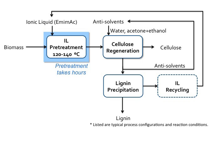
Schematic of IL (EmimAc) pretreatment flow diagram.
Biomass enters IL pretreatment (120-140 C) with EmimAC. This pretreatment takes hours. After pretreatment the products head to cellulose regeneration which washes the products with anti-solvents (water, acetone+ethanol). The cellulose is extracted, and the remaining products go into lignin precipitation which precipitates the lignin and recycles the anti-solvents and IL.
4.3g Biological Pretreatment
4.3g Biological PretreatmentThe last technology we will look at is biological pretreatment. Lignin is removed from lignocellulosic biomass through lignin-degrading microorganisms. Key parameters are temperature, cultivation time, nutrient addition, and selectivity on lignin. Some of the lignin-degrading enzymes include lignin peroxidase, manganese peroxidase, laccase, and xylanase. Advantages to using a system such as this include: no chemicals, mild conditions (ambient temperature and pressure), low energy and low capital outlay, and less enzyme use later on. However, pretreatments take days to weeks, loss of cellulose and hemicellulose, contaminants, and additional pretreatment for higher sugar yield.
4.3h Summary
4.3h SummaryOf the methods we’ve discussed, there are pretreatment options that lead the others (some under commercialization). The current leading pretreatment options include dilute acid, AFEX, liquid hot water, lime, and aqueous ammonia, with dilute acid and water, AFEX, and lime under commercialization. The figure below shows switchgrass before pretreatment and after several pretreatment options, i.e., AFEX, dilute acid, liquid hot water, lime, and soaking in aqueous ammonia (SAA).

The Resulting Switchgrass Solids after Different Pretreatment Technologies.
The image displays six samples of switchgrass, each subjected to a different pretreatment method, arranged side by side for visual comparison. The samples are labeled from A to F, with each label corresponding to a specific treatment:
- A. Control – Untreated switchgrass, serving as the baseline for comparison.
- B. AFEX – Treated with Ammonia Fiber Expansion, a method used to enhance biomass digestibility.
- C. Dil. Acid – Treated with dilute acid, commonly used to break down hemicellulose and improve enzymatic access.
- D. LHW – Treated with Liquid Hot Water, a hydrothermal method that disrupts plant cell wall structure.
- E. Lime – Treated with calcium hydroxide (lime), which helps in delignification and cellulose exposure.
- F. SAA – Treated with Sulfite-Assisted Alkaline pretreatment, aimed at removing lignin and enhancing cellulose accessibility.
A scale bar in the bottom right corner indicates 5 mm, providing a reference for the size and physical changes in the switchgrass samples due to each treatment. The image highlights the visual differences in texture, color, and structure among the treated and untreated samples, which are important for evaluating the effectiveness of each pretreatment method in biofuel or biochemical production processes.
To summarize the methods of pretreatment, the table below shows some of these pretreatment methods and the major and minor effects on lignocellulosic biomass. All methods (AFEX, dilute acid, lime, liquid hot water, soaking aqueous ammonia, and treatment with SO2) affect increasing surface area, removing hemicellulose, and altering lignin structure. Only AFEX, lime, and SAA pretreatments remove lignin, and AFEX and SAA decrystallize cellulose.
| Pretreatment | Increases Accessible Surface Area | Decrystallizes Cellulose | Removes Hemicellulose | Removes Lignin | Alters Lignin Structure |
|---|---|---|---|---|---|
| AFEX | Major Effect | Major Effect | Minor Effect | Major Effect | Major Effect |
| Dilute Acid | Major Effect | - | Major Effect | - | Major Effect |
| Lime | Major Effect | Not Determined | Minor Effect | Major Effect | Major Effect |
| Liquid H2O | Major Effect | Not Determined | Major Effect | - | Minor Effect |
| SAA | Major Effect | Major Effect | Minor Effect | Major Effect | Major Effect |
| SO2 | Major Effect | - | Major Effect | - | Minor Effect |
This table shows the conditions for ideal pretreatment of lignocellulosic biomass for dilute acid, steam explosion, AFEX, and liquid hot water.
| Pretreatment Process | Dilute Acid | Steam Explosion | AFEX | Liquid Hot Water |
|---|---|---|---|---|
| Reactive Fiber | Yes | Yes | Yes | Yes |
| Particle Size Reduction Required | Yes | No | Nob | No |
| Hydrolyzate Inhibitory | Yes | Yes | No | Slightly |
| Pentose Recovery | Moderate | Low | High | High |
| Low-Cost Materials of Construction | No | Yes | Yes | Yes |
| Production of Process Residues | Yes | No | No | No |
| Potential for Process Simplicity | Moderate | High | Moderate | High |
| Effectiveness at Low Moisture Contents | Moderate | High | Very High | Not Known |
a Modified from (86); AFEX ratings from Bruce Dale (personal communication).
b For grasses, data for wood not available.
Credit: Lynd, 1996. Annual Rev. Energy Environ., 21: 403-465
4.4 Assignments Overview
4.4 Assignments OverviewExam #1
You will complete Exam #1.
4.5 Summary and Final Tasks
4.5 Summary and Final TasksSummary
Lesson 5 covered biomass pyrolysis and biomass pretreatment. Pyrolysis is a thermal treatment in the absence of oxygen and at lower temperature than gasification. The main products of interest are chars that are often used in combustion (with some of the undesirable components removed), and liquids that need to be processed further to remove oxygen functionality and add hydrogen.
The goal of pretreatment is to overcome biomass recalcitrance and improve conversion efficiency/economics. Mechanical size reduction is generally required. Several pretreatment technologies have been developed based on the use of different chemicals. They do the following:
- Low pH pretreatment: hemicellulose removal, acetyl removal, lignin solubilization and re-precipitation, increased surface area
- High pH pretreatment: lignin removal, acetyl removal, hemicellulose solubilization, increased surface area
- AFEX pretreatment: no compositional changes, lignin alternation, cellulose decrystallization, increased surface area
- Organosolv and IL: fractionation of lignin from cellulose and hemicellulose, increased surface area
Lesson Objectives Review
By the end of this lesson, you should be able to:
- explain how pyrolysis is different from gasification and combustion;
- explain how the products are made and used as fuels and chemicals;
- determine which thermal process is best to use depending on biomass source and product utilization;
- describe the basic chemical structures of biomass, namely lignocellulosic biomass;
- evaluate pretreatment options for lignocellulosic options and explain why they are necessary.
- References
Schobert, H.H., Energy and Society: An Introduction, 2002, Taylor & Francis: New York, Ch. 4-6.
He, Brian, Department of Biological and Agricultural Engineering, University of Idaho, BEEMS Module C2, Biomass Pyrolysis, sponsored by USDA Higher Education Challenger Program, 2009-38411-19761, PI on project Li, Yebo.
Shi, Jian, Hodge, D.B., Pryor, S.W., Li, Yebo, Department of Food, Agricultural, and Biological Engineering, The Ohio State University, BEEMS Module B1, Pretreatment of Lignocellulosic Biomass, sponsored by USDA Higher Education Challenger Program, 2009-38411-19761, PI on project Li, Yebo.
Reminder - Complete all of the Lesson tasks!
You have reached the end of the Lesson. Double-check the Road Map on the Lesson Overview page to make sure you have completed the activity listed there before you begin the next Lesson.
Questions?
If there is anything in the lesson materials that you would like to comment on, or don't quite understand, please post your thoughts and/or questions to our Throughout the Course Questions & Comments discussion forum. The discussion forum will be checked regularly (Monday through Friday). While you are there, feel free to post responses to your classmates if you can help.