Lesson 3: Use of Biomass in Thermal Technologies
Lesson 3: Use of Biomass in Thermal TechnologiesOverview
In the last few lessons, we’ve learned about why current society is considering the use of biomass and the current methods of generating transportation fuels and electricity from fossil sources. With this lesson, we are moving into the use of biomass in various ways. This lesson focuses on thermal processes (both to generate electricity and liquid fuels), using biomass rather than coal, petroleum, or natural gas. Different fuels are produced from gasification and pyrolysis, so we will determine how each must be processed and utilized for fuel.
Lesson Objectives
By the end of this lesson, you should be able to:
- explain how wood was used historically to produce heat and electricity;
- evaluate the difference between combustion and gasification, and explain how design features differ depending on the process;
- evaluate how pyrolysis is different from gasification;
- describe the utilization of products from gasification versus pyrolysis, including how the processing of products differs.
Lesson 3 Road Map
This lesson will take us one week to complete. Please refer to the Course Syllabus for specific time frames and assignment due dates.
Questions?
If there is anything in the lesson materials that you would like to comment on or don't quite understand, please post your thoughts and/or questions to our Throughout the Course Questions and Comments discussion forum. The discussion forum will be checked regularly. While you are there, feel free to post responses to your classmates if you are able to help. Regular office hours will be held to provide help for EGEE 439 students.
3.1 Wood
3.1 WoodHistory of Burning Wood
Wood has been used as a source of energy for thousands of years (the first known use of fire was determined when archeologists made discoveries of humans living 400,000 years ago), and wood was the obvious source to make fire. In the Americas, in 1637, the people of Boston suffered from the scarcity of wood. It became America’s first energy crisis after less than one century of settlement. During the late 1700s, Benjamin Franklin invented a cast iron stove for indoor use. It held heat in the room after the fire burned out. However, it had a design flaw in that it had no way to pull in air, so fires went out quickly. So David R. Rittenhouse added a chimney and exhaust pipe to improve upon it.
Burning Wood
First, we will look at where energy is stored in materials, starting with the methane molecule. The combustion of methane is exothermic (releases heat as the reaction proceeds), but the reaction must be initiated before it will sustain itself with the continued availability of methane and oxygen. The formula below shows the reaction in a stoichiometric format:
The figure below shows the same reactants and products, but with the bonds before reaction and after the reaction, on a molecular/atomic level. The number of atoms in each molecule doesn't change, but how they are arranged and connected does. The only real change is how the atoms are linked - these are the chemical bonds. Since ENERGY comes out of a burning system, then it must mean that more energy is stored in 4 C-H bonds and 2 O-O bonds than in 4 H-O and two C-O bonds. The ENERGY released during chemical combustion comes from ENERGY stored in chemical bonds of fuel & oxygen.

The 1 Methane and 2 oxygen reaction shows bond connections before and after the combustion reaction.
Reactants: Methane will react with two oxygen molecules. All of the four hydrogens in methane are connected to a single carbon atom by 4 single bonds. The oxygen molecules are each two oxygen atoms connected by a double bond.
During combustion, the atoms rearrange and form new bonds.
Products: The carbon atom connects to 2 oxygen atoms with a double bond between the carbon and each oxygen to produce one carbon dioxide molecule. Additionally, each of the other remaining oxygen atoms forms 2 single bonds to 2 of the remaining hydrogen atoms to form a water molecule. The net products of the reaction are 1 CO2 molecule and 2H2O molecules.
We now know the reaction chemistry of methane combustion, but wood is a much more complex material than methane. Wood contains up to 50% water. Water in the wood will reduce the heating value of the wood, and if the wood is very wet, it will lead to a smoky fire. The main components of wood (we will cover this in more depth in a later lesson) are cellulose (what paper is made from) and lignin (the part of a tree that makes it have a sturdy structure). In order to start a fire, you typically must ignite a material that burns easily to begin heating the wood (this can be newspaper or a “fire starter”). The components begin to decompose from the heat (therefore we are not technically “burning” yet), which produces vapors and char. The vapors are called “volatiles” and the char is composed of carbon and ash. The volatiles are what actually begin to burn, producing a flame. The carbon-rich char produces glowing embers or “coals,” which are needed to keep the fire sustained. Wood does not typically contain sulfur, so no sulfur oxides (or SOx) are produced.
There can be problems with burning wood. The smoke comes from particulates that did not burn or only partially burned which can pollute the atmosphere, and typically come from resins in the trees. It isn’t an issue when one or two people are burning wood, but when thousands of people burn wood in fireplaces. In State College, Pennsylvania, in the winter, one can see smoke in the air from fireplaces. Wood fires in fireplaces can also deposit soot and creosote in the chimneys, which if not cleaned periodically, can ignite. Burning wood (or really most things) will produce an ash material (minerals in wood and coal that react with air under combustion conditions); the ash must be disposed of. Wood smoke also contains a variety of chemicals that can be carcinogenic.
Now let’s begin discussing different biomass sources, how we measure different properties of different biomasses, and how to determine the atomic composition of biomass.
3.2 Biomass
3.2 BiomassThere are four types of biomass resources that can be utilized:
- agricultural residues
- energy crops
- forestry residues
- processing wastes
Examples of different sources are listed below:
Agricultural Residues:
- Corn stover
- Wheat straw
- Rice straw
- Soybean stalk
Energy Crops:
- Switchgrass
- Sweet sorghum
- Sugar canes
- Algae
- Cattail
- Duckweed
Forestry Residues:
- Saw dust
- Woody chips
Processing wastes:
- Food processing wastes
- Animal wastes
- Municipal solid wastes
As already mentioned, most biomass is at least partially composed of three components: cellulose, hemicellulose, and lignin. The figures below show a diagram of lignocellulose and the biomass broken down into three parts. There will be significantly more discussion on biomass composition in future lessons. Cellulose is a crystalline polymer of ring molecules (6 carbons) with OH and COOH groups (in the first figure below, cellulose is the straight green lines; in the second figure it is the green molecule). Hemicellulose is similar, but has ring molecules with 5 and 6 carbons, and is amorphous in structures, as depicted in the first figure below by the black squiggly line; The second figure shows how it is around the cellulose and more detail of the molecular structure. Lignin is the material that holds it all together and is the light blue line in the first figure below and it is in red in the second figure.

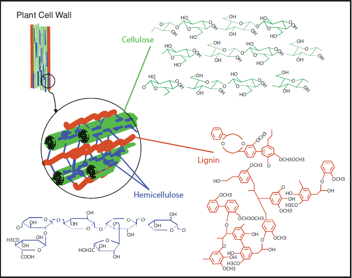
The image is a detailed scientific diagram illustrating the biomass and its three primary components: cellulose, hemicellulose, and lignin. On the left side, the plant cell wall is shown in a magnified view, revealing how these components are arranged within the wall's matrix.
Cellulose is represented in green and is shown as long, linear chains that form microfibrils, providing structural strength. Its chemical structure is displayed in the top right corner of the image.
Hemicellulose is depicted in blue and appears as shorter, branched polysaccharides that interact with cellulose fibers, helping to cross-link the cell wall components. Its chemical structure is shown in the bottom left corner.
Lignin is illustrated in red and is shown filling the spaces between cellulose and hemicellulose, adding rigidity and resistance to degradation. Its complex, aromatic chemical structure is displayed in the bottom right corner.
How To Determine Properties of Biomass
There are four common ways to measure the properties of any carbon product, which will also be used for biomass: 1) proximate analysis, 2) ultimate analysis, 3) heat of combustion, and 4) ash analysis.
Proximate analysis
Proximate analysis is a broad measurement to determine the moisture content (M), volatile matter content (VM), fixed carbon content (FC), and ash content. These are all done on a mass basis, typically, and are done in what is called a proximate analyzer – the analyzer just measures the mass loss at certain temperatures. Moisture is driven off at ~105-110°C (just above the boiling point of water); it represents physically bound water only. Volatile matter is driven off in an inert atmosphere at 950°C, using a slow heating rate. The ash content is determined by taking the remaining material (after VM loss) and burning it at above 700°C in oxygen. The fixed carbon is then determined by the difference: FC = 1 – M – Ash – VM.
The following is an example of proximate analysis of lignin, which is part of wood and/or grasses, primarily:
- Moisture (wt%): 5.34
- Ash (wt%): 14.05
- Volatile Matter (wt%): 60.86
Sometimes the moisture content will be removed from the VM and ash contents, on a dry basis:
Ultimate analysis
The ultimate analysis is more specific in that it analyzes the elemental composition of the organic portion of materials. The compositions of carbon (C), hydrogen (H), nitrogen (N), sulfur (S), and oxygen (O) are determined on a mass percent basis and can be converted to an atomic basis. In some cases, chlorine (Cl) will also be analyzed. There are instruments that are designed to measure only the C H N mass percent and then another to measure the S percent; the instrument combusts the material and measures the products of combustion. The following is an example problem for determining the molecular atomic composition of biomass when being provided with an ultimate analysis. Oxygen is usually determined by difference. Water can skew the hydrogen results and must be accounted for.
Your Turn
Problem 1:
The ultimate analysis shows that the C, H, O, N, and S contents of a biomass material are 51.9%, 5.5%, 41.5%, 0.8%, and 0.3% on a dry basis. What is the chemical formula of this biomass? How many kilograms of air are required to completely combust 1 kg of this biomass? The results are shown below.
The following examples are of the calculation of Problem 1, the chemical formula of biomass, when given mass percent on a dry basis. If you know the elemental mass percent of the sample, you can divide it by the molecular weight to determine the atomic value of each element. The values in the table are then divided by the atomic number of carbon to normalize the molecule. So, for every carbon, you have 1.26 atoms of hydrogen, 0.6 atoms of oxygen, etc.
| Values | |
|---|---|
Heat of combustion
The heat of combustion can be measured directly using a bomb calorimeter. This instrument is used to measure the calorific value per mass (calorie/gram or Btu/lb). It can also be estimated using different formulas that calculate it based on either ultimate or proximate analysis. A common type of calorimeter is the isoperibol calorimeter, which will contain the heat inside the jacket but will accommodate the change in temperature of the water in the bucket; see the schematic below. A sample is placed in a crucible that is put inside of a reactor with high-pressure oxygen. The sample is connected to a fuse and electrical leads that will ignite the sample, all contained within the reactor (sometimes called a bomb calorimeter). The water temperature in the bucket is measured before and after ignition, and with all the other parts calibrated, the specific heat of the water and the change in temperature are used to determine the heat of combustion.
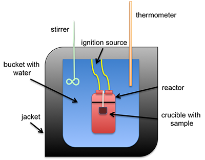
Schematic of isoperibol calorimeter.
This is a schematic of an isoperibol calorimeter. There is a crucible containing a sample. Both sit inside a reactor. The reactor itself is in a bucket with water that has an insulating jacket on the outside, including the top. Sticking into the water are a stirrer and a thermometer. The reaction is started by an ignition source connected to the reactor.
The heating value is determined in a bomb calorimeter. Heating values are reported on both wet and dry fuel bases. For the high heating value (HHV), the value can be determined by normalizing out the moisture in a liquid form. For the low heating value (LHV), a portion of the heat of combustion is used to evaporate the moisture.
Ash Analysis
The minerals in the material, once combusted, turn to ash. The ash can be analyzed for specific compounds that will contain oxygen, such as CaO, K2O, Na2O, MgO, SiO2, Fe2O3, P2O5, SO3, and Cl. The original minerals can also be measured. Once the mineral or ash is isolated, it often must be dissolved in various acids and then analyzed. There is other instrumentation available, but the analysis is quite complicated and not often done.
Bulk density is also determined for biomass as a property. It is typically determined by measuring the weight of material per unit volume. It is usually determined on a dry weight basis (moisture-free) or on an as-received basis with moisture content available. For biomass, the low values (grain straws and shavings) are 150-200 kg/m3 (0.15-0.20 g/cm3), and the high values (solid wood) are 600-900 kg/m3 (0.60-0.90 g/cm3). The heating value and bulk density are used to determine the energy density. The figure below shows a comparison of various biomass sources to fossil fuel sources on an energy density mass basis.

Many of the fuel characteristics we have been discussing need to be known for the proper use of biomass in combustion, gasification, and other reaction chemistry.
3.3 Gasification
3.3 GasificationNow, we will go into gasification and compare it to combustion. Gasification is a process that produces syngas, a gaseous mixture of CO, CO2, H2, and CH4, from carbonaceous materials at high temperatures (750 – 1100°C). Gasification is a partial oxidation process; the reaction takes place with a limited amount of oxygen. The overall process is endothermic (requires heat to keep the reaction going), so it requires either the simultaneous burning of part of the fuel or the delivery of an external source of heat to drive the process.
Historically, gasification was used in the early 1800s to produce lighting, in London, England (1807) and Baltimore, Maryland (1816). It was manufactured from the gasification of coal. Gasification of coal, combined with Fischer-Tropsch synthesis was one method that was used during WWII to produce liquid fuel for Germany because they did not have access to oil for fuel. It has also been used to convert coal and heavy oil into hydrogen for the production of ammonia and urea-based fertilizers. As a process, it continues to be used in South Africa as a source of liquid fuels (gasification followed by Fischer-Tropsch synthesis).
Gasification typically takes place at temperatures from 750-1100°C. It will break apart biomass (or any carbon material), and usually, an oxidizing agent is added in insufficient quantities. The products are typically gas under these conditions, and the product slate will vary depending on the oxidizing agent. The products are typically hydrogen, carbon monoxide, carbon dioxide, and methane. There may also be some liquid products depending on the conditions used. Gasification and combustion have some similarities; the figure below shows the variation in products between gasification and combustion. The table shows a comparison of the conditions.

| Specification | Combustion | Gasification |
|---|---|---|
| Oxygen Use | Uses excess | Uses limited amounts |
| Process Type | Exothermic | Endothermic |
| Product | Heat | Combustible Synthesis |
Zones of Gasification
There are several zones that the carbon material passes through as it proceeds through the gasifier:
- drying
- pyrolysis
- combustion
- reduction
The schematic below shows the zones and the products that typically occur during that part of the process. First, we will discuss what happens in each zone. We will also be looking at different gasifier designs to show these zones change depending on the design, and each design has advantages and disadvantages.
The drying process is essential to remove surface water, and the “product” is water. Water can be removed by filtration, evaporation, or a combination of both. Typically, waste heat is used to do the evaporation.

General schematic of different regions in a gasifier.
Diagram showing different regions and products in a gasifier. Heat is applied to the entire system, oxidizing agents such as air, O2, H2O, and CO2 enter from the bottom and biomass enters from the top.
The biomass first goes through drying which removes water. It then goes through pyrolysis which produces char, tar, and methane. From pyrolysis, the biomass can go to reduction or combustion which produces carbon dioxide and water. If the biomass goes through combustion it also then goes to reduction which produces hydrogen gas and carbon monoxide.
Pyrolysis is typically the next zone. If you look at it as a reaction:
where x is the mass fraction of tars in the volatiles. Volatile gases are released from the dry biomass at temperatures ranging up to about 700oC. These gases are non-condensable vapors such as CH4, CO, CO2, and H2 and condensable vapor of tar at the ambient temperature. The solid residues are char and ash. A typical method to test how well a biomass material will pyrolyze is thermogravimetric analysis; it is similar to the proximate analysis. However, the heating rate and oxidizing agent can be varied, and the instrument can be used to determine the optimum temperature of pyrolysis.
Gasification Process and Chemistry: Combustion and Reduction
A limited amount of oxidizing agent is used during gasification to partially oxidize the pyrolysis products of char (C), tar, and gas to form a gaseous mixture of syngas mainly containing CO, H2, CH4, and CO2. Common gasifying agents are air, O2, H2O, and CO2. If air or oxygen is used as a gasifying agent, partial combustion of biomass can supply heat for the endothermic reactions.
Combustion of gases:
The equivalence ratio (ER) is the ratio of O2 required for gasification, to O2 required for full combustion of biomass. The value of ER is usually 0.2 - 0.4. At too high ER values, excess air causes unnecessary combustion of biomass and dilutes the syngas. At too low ER values, the partial combustion of biomass does not provide enough oxygen and heat for gasification.
There are several reactions that can take place in the reduction zone. There are three possible types of reactions: 1) solid-gas reactions, 2) tar-gas reactions, and 3) gas-gas reactions. Essentially, H2O and CO2 are used as gasifying agents to increase the H2 and CO yields. The double-sided arrow represents that these reactions are reversible depending on the conditions used.
Solid-gas reactions include:
Tar-gas reactions include:
Gas-gas reactions include:
The reactions can be affected by reaction equilibrium and kinetics. For a long reaction time: 1) chemical equilibrium is attained, 2) products are limited to CO, CO2, H2, and CH4, and 3) low temperatures and high pressures favor the formation of CH4, whereas high temperatures and low pressures favor the formation of H2 and CO. For a short reaction time: 1) chemical equilibrium is not attained, 2) products contain light hydrocarbons as well as up to 10 wt% heavy hydrocarbons (tar), and 3) steam injection and catalysts can shift the products toward lower molecular weight compounds.
Gasifier Designs
There are several types of gasifier designs:
- updraft
- downdraft
- cross downdraft
- fluidized bed
- plasma
The first type of gasifier is the updraft design. The advantages include that it is a simple design and is not sensitive to fuel selection. However, disadvantages include a long start-up time, production of high concentrations of tar, and a general lack of suitability for modern heat and power systems.
The downdraft gasifier is similar, but the air enters in the middle of the unit and gases flow down and out. The oxidation and reduction zones change places. Advantages of this design include low tar production, low power requirements, a quicker response time, and a short start-up time. However, it has a more complex design, fuel can be fouled with slag, and it cannot be scaled up beyond 400 kg/h.

Updraft design gasifier.
Schematic of an Updraft Gasifier. The diagram looks like a cylinder with oxidizing gas entering at the bottom and flowing up and out at the top. There are 5 layered zones in the gasifier. Starting at the bottom there is the ash zone, the oxidation zone, the reduction zone, the pyrolysis zone, and the drying zone.

Downdraft design gasifier.
Schematic of a downdraft gasifier. The diagram again looks like a cylinder and again has 5 layered zones. From the bottom up they are the ash pit, the reduction zone, the oxidation zone, the pyrolysis zone, and the drying zone. The air enters in the middle of the gasifier at the oxidation zone and the air flows down and comes out the bottom as product gas.
The crossdraft design gasifier is similar to the downdraft, it has a quicker response time and a short start-up time; it is also complex in design, cannot use high mineral-containing fuels, and fuel can be contaminated with slag from ash.
With a fluidized bed design gasifier, the action of this gasifier is similar to how water might boil, except the air (or other gas) flows through the fines (the sample and sand) at temperature, creating a bubbling effect similar to boiling. Because of this action, it has the advantages of greater fuel flexibility, better control, and a quick response to changes. But because of these advantages, these types of gasifiers have a higher capital cost, and a higher power requirement, and must be operated on high particulate loading.

Crossdraft design gasifier.
Schematic of a crossdraft gasifier. This gasifier again looks like a cylinder and has all 5 of the zones the previous 2 did. However, instead of layers, the zones look more like a bullseye. Air enters halfway up the cylinder in the very center which is the oxidation zone. Around the oxidation zone is the reduction zone and outside that is the pyrolysis zone. The drying zone is around them all. The ash pit is still a layer at the very bottom. Product gas comes out at the same level the air initially came in.

Fluidized bed design gasifier.
Schematic of a fluidized bed design gasifier. This gasifier looks like a cylindrical capsule where air, oxygen or steam enters from the bottom. Near the bottom, there is a distributor plate. The fluidized bed with the fuel sits on top of the plate and at the bottom of the fluidized bed, there is an exit for the ash. There is a mechanism to recirculate the fines near the top of the fluidized bed. To exit, the gas flows through a cyclone and out the top of the gasifier.
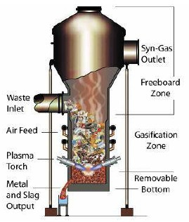
One of the new design gasifiers is a plasma gasifier design. Plasma gasification uses extremely high temperatures in an oxygen-starved environment to decompose waste material into small molecules and atoms so that the compounds formed are very simple and form syngas with H2, CO, and H2O. This type of unit functions very differently, as electricity is fed to a torch that has two electrodes – when functioning, the electrodes create an arc. Inert gas is passed through the arc, and, as this occurs, the gas heats to temperatures as high as 3,000 °C (Credit: Westinghouse Plasma Corporation). The advantages of such units include:
- process versatility
- superior emission characteristics
- no secondary treatment of byproducts
- valuable byproducts
- enhanced process control
- volume reduction of material fed
- small plant size
Units such as these are more expensive and scaling up is still in the research stage. These types of units are most commonly used for municipal waste sludge.

Plasma Design Gasifier.
Schematic of a plasma design gasifier. This looks like a funnel with a lid. About halfway up there is a waste inlet. Below that there is an inlet for air or oxygen and near the bottom there are plasma torches. The syngas exits from an outlet at the top and slag and recovered metals are collected from an outlet at the bottom.
General information on gasification
So what products are made, what advantages are there to using various oxidizing sources, how are the byproducts removed, and how is efficiency improved? Besides syngas, other products are made depending on the design. As stated previously, the syngas is composed of H2, CO, CO2, H2O, and CH4. Depending on the design, differing amounts of tar and char can also be made. For example, for steam fluidized gasification of wood sawdust at atmospheric pressure and 775°C, 80% of the carbon will be made into syngas, 4% of the carbon will produce tar, and 16% will produce char (Herguido J, Corella J, Gonzalez-Saiz J. Ind Eng Chem Res 1992; 31: 1274-82.)
There are multiple uses for syngas, for making hydrocarbon fuels, for producing particular chemicals, and for burning as a fuel; therefore, syngas has a heating value. The heating value can be calculated by the volumetric fraction and the higher heating values (HHV) of gas components, which is shown in this equation:
where:
A problem based on this equation and HHVs will be included in the homework.
Other factors are determined for optimal gasification. Thermal efficiency is the conversion of the chemical energy of solid fuels into chemical energy and sensible heat of gaseous products. For high-temperature/high-pressure gasifiers, the efficiency is high, ~90%. For typical biomass gasifiers, the efficiency is reduced to 70-80% efficiency. Cold gas efficiency is the conversion of the chemical energy of solid fuel to the chemical energy of gaseous products; for typical biomass gasifiers, the efficiency is 50-60%.
There are several processing factors that can affect different aspects of gasification. The following table shows the main advantages and technical challenges of different gasifying agents. Steam and carbon dioxide as oxidizing agents are advantageous in making high-heating value syngas with more hydrogen and carbon monoxide than other gases but also require external heating sources and catalytic tar reformation.
| Gasifying Agent | Main Advantages | Main Technical Challenges |
|---|---|---|
| Air | Partial combustion for heat supply of gasification. Moderate char and tar content. | Low heating value (3-6 MJ/Nm3) Large amount of N2 in syngas (i.e., >50% by volume) Difficult determination of equivalence ratio (ER) |
| Steam | High heating value syngas (10-15 MJ/Nm3) H2-rich syngas (i.e., >50% by volume) | Requires indirect or external heat supply for gasification High tar content in syngas Tar requires catalytic reforming to syngas unless used to make chemicals |
| Carbon dioxide | High heating value syngas High H2/CO and low CO2 in syngas | Requires indirect or external heat supply Tar requires catalytic reforming to syngas unless used to make chemicals |
Basic design features can also affect the performance of a gasifier. The table below shows the effect of a fixed bed versus a fluidized bed and the differences in temperature, pressure, and equivalence ratio. Fixed/moving beds are simpler in design and favorable on a small scale economically, but fluidized bed reactors have higher productivity and low byproduct generation. The rest of the table shows how increased temperature can also favor carbon conversion and the HHV of the syngas, while increased pressure helps with producing high-pressure syngas without compression to higher pressures downstream.
| Bed Design | Main Advantages | Main Technical Challenges |
|---|---|---|
| Fixed/moving bed | Simple and reliable design Favorable economics on a small scale | Long residence time Non-uniform temperature distribution in gasifiers High char and/or tar contents Low cold gas efficiency Low productivity (i.e., ~5 GJ/m2h) |
| Fluidized bed | Short residence time High productivity (i.e., 20-30 GJ/m2h) Uniform temperature distribution in gasifiers Low char and/or tar contents High cold gas efficiency Reduced ash-related problems | High particulate dust in syngas Favorable economics on a medium to large scale |
| Increase of temperature | Decreased tar and char content Decreased methane in syngas Increased carbon conversion Increased heating value of syngas | Decreased energy efficiency Increased ash-related problems |
| Increase of pressure | Low tar and char content No costly syngas compression is required for downstream utilization of syngas | Limited design and operational experience Higher cost of gasifier at small scale |
| Increase of ER (Equivalence Ratio) | Low tar and char content | Decreased heating value of syngas |
Product Cleaning
The main thing that has to be done to clean the syngas is to remove char and tar. The char is typically in particulate form, so the particulates can be removed in a way similar to what was described in the power plant facility. Typically for gasifiers, the method of particulate filtration includes gas cyclones (removal of particulate matter larger than 5 μm). Additional filtration can be done using ceramic candle filters or moving bed granular filters.
Tars are typically heavy liquids. In some cases, the tars are removed by scrubbing the gas stream with a fine mist of water or oil; this method is inexpensive but also inefficient. Tars can also be converted to low molecular weight compounds by “cracking” into CO and H2 (these are typically the desired gases for syngas). This is done at high temperature (1000°C) or with the use of a catalyst at 600-800°C. Tars can also be “reformed” to CO and H2, which can be converted into alcohols, alkanes, and other useful products. This is done with steam and is called steam reforming of tar; the reaction conditions are at a temperature of ~250°C and pressure of 30-55 atm. The reaction is shown below and is the same reaction as that shown in reaction 11:
Tar steam reforming reaction:
Steam reforming has advantages. It is generally a safer operation since there isn’t any oxygen in the feed gases, and it produces a higher H2/CO ratio syngas product than most alternatives. The main disadvantage is a lower thermal efficiency, as heat must be added indirectly because the reaction is endothermic.
Syngas Utilization
As stated earlier, syngas has multiple uses. Syngas can be used to generate heat and power, and can even be used to turn a turbine in some engineering designs. Syngas can also be used as the synthesis gas for Fischer-Tropsch fuel production, synthesis of methanol and dimethyl ether (DME), fermentation for the production of biobased products, and production of hydrogen.
So, how is syngas utilized in heat and power generation? Syngas can be used in pulverized coal combustion systems; it help the coal to ignite and to prevent the plugging of the coal feeding system. Biomass gasification can ease ash-related problems. This is because the gasification temperature is lower than in combustion, and once gasified, can supply clean syngas to the combustor. Adding a gasifier to a combustion system helps in the utilization of a variety of biomass sources with large variations in properties. Once the syngas has been cleaned, it can be fed to gas engines, fuel cells, or gas turbines for power generation.
Syngas may also be used to produce hydrogen. When biomass is gasified, a mixture of H2, CO, CH4, and CO2 is produced. Further reaction to hydrogen can be done using water reforming and water-gas shift reactions:
Water reforming reaction for CH4 to H2:
Water-gas shift reaction for CO to H2 (as shown earlier):
Carbon dioxide may also be removed, as it is typically an undesirable component. One method to keep it from going into the atmosphere is to do chemical adsorption:
Syngas can also be utilized for the Fischer-Tropsch synthesis of hydrocarbon fuels. Variable chain-length hydrocarbons can be produced via a gas mixture of CO and H2 using the Fischer-Tropsch method. The reaction for this is:
In order for the reaction to take place, the ratio should be close to 2:1, so gases generated via gasification may have to be adjusted to fit this ratio. Inert gases also need to be reduced, such as CO2, and contaminants such as H2S, as the contaminants may lower catalyst activity.
Methanol and dimethyl ether can also be produced from syngas. The reactions are:
Dimethyl ether (DME) can be made from methanol:
Syngas can also be fermented to produce bio-based products. This will be discussed in detail in a later lesson.
3.4 Assignments Overview
3.4 Assignments OverviewHomework #1
Download and complete Homework #1. It contains questions that pertain to this lesson's course material. Convert to pdf format. Be sure to show your work! When you are finished, upload your completed assignment to Homework#1 Dropbox in Canvas. Use the following naming convention for your assignment: your user ID_HW1 (i.e., ceb7_HW1).
3.5 Summary and Final Tasks
3.5 Summary and Final TasksSummary
There are several potential crops that can be utilized for combustion and gasification. These include energy crops, crop residues, forest residues, and process wastes. These can be utilized in both combustion processes and gasification processes. For gasification, we looked at several factors:
- gasification process and chemistry
- gasifier design and operation
- syngas cleaning
- syngas utilization to make a variety of products
Biobased energy and chemical products discussed in the lesson include:
- heat and power
- hydrogen
- F-T hydrocarbon fuels
- alcohols
- biochemical and biopolymers.
Lesson Objectives Review
By the end of this lesson, you should be able to:
- explain how wood was used historically to produce heat and electricity;
- evaluate the difference between combustion and gasification, and explain how design features differ depending on the process;
- evaluate how pyrolysis is different from gasification;
- describe the utilization of products from gasification versus pyrolysis, including how the processing of products differs.
References
Schobert, H.H., Energy and Society: An Introduction, 2002, Taylor & Francis: New York, Ch. 4-6.
Wang, L., Biological Engineering, North Carolina A&T University, BEEMS Module C1, Biomass Gasification, sponsored by USDA Higher Education Challenger Program, 2009-38411-19761, PI on project Li, Yebo.
Questions?
If there is anything in the lesson materials that you would like to comment on, or don't quite understand, please post your thoughts and/or questions to our Throughout the Course Questions Comments discussion forum and/or set up an appointment for office hour. The discussion forum is checked regularly (Monday through Friday). While you are there, feel free to post responses to your classmates if you are able to help.