Lesson 9: Heating
Lesson 9: HeatingThe links below provide an outline of the material for this lesson. Be sure to carefully read through the entire lesson before returning to Canvas to submit your assignments.
9.1 Lesson 9 Introduction
9.1 Lesson 9 IntroductionWelcome to Lesson 9
In this module, we will explore the science, technology, and economics of keeping homes warm. Whether you're living in a dorm, renting your first apartment, or planning for homeownership, understanding how heating works—and how to use it efficiently—can save you money, increase your comfort, and reduce your environmental impact.
But before we dive into furnaces, heat pumps, and fuel choices, we need to answer two foundational questions:
How much heating does my location actually need?
How do I keep that heat from escaping?
The answers lie in two powerful concepts: Heating Degree Days which is a way to measure climate-based heating demand and Insulation which is the barrier that keeps warmth where you want it.
Once we understand those basics, we'll compare different heating systems, analyze fuel costs, and learn how to calculate whether an energy upgrade is worth the investment.
Learning Objectives
By the end of this module, you will be able to:
- Define the three mechanisms of heat transfer: conduction, convection, and radiation
- Explain what Heating Degree Days (HDD) are and why the base temperature is 65°F
- Describe how insulation works and what R-Value measures
- Identify common home heating fuels (natural gas, oil, propane, electricity) and their typical uses by region
- Calculate daily, monthly, and seasonal Heating Degree Days using average temperature data
- Compare insulation materials using R-Value and explain how layered construction improves thermal resistance
- Calculate simple payback periods for energy upgrades to determine if an investment is financially worthwhile
9.2 Mechanisms of Heat Transfer
9.2 Mechanisms of Heat TransferHeat transfer is the movement of thermal energy from a hotter system to a colder system. This process is driven by temperature differences and is classified into three different mechanisms: conduction, convection and radiation.
Conduction
Conduction is the transfer of heat through direct contact between particles in a solid object. Heat moves from the warmer area to the cooler area through particle collisions.
In solids, atoms and molecules cannot move freely like they do in liquids or gases. Instead, they vibrate in place. When an atom or molecule gains energy, it vibrates more vigorously and transfers that energy to neighboring atoms through physical contact.
Example: In the image below, heat travels from the end of a metal rod in a candle flame to the cooler end. The vibrations pass from one molecule to the next, but the molecules themselves do not move from their positions.
Convection
Convection is the transfer of heat through the movement of fluids (liquids or gases).
In residential heating, convection occurs when warm air rises and cold air sinks. When you open a door, warm indoor air escapes outside while cold air enters through cracks around windows and doors. Inside a room, cold air near the floor absorbs heat from the heater, becomes less dense, and rises. Meanwhile, heavier cold air sinks to take its place, creating a circulation pattern that gradually warms the entire room.
In the image below, heat (energy) is conducted from the end of the rod in the candle flame further down to the cooler end of the rod as the vibrations of one molecule are passed to the next; however, there is no movement of energetic atoms or molecules.
Radiation
Radiation is the transfer of heat through electromagnetic waves. Unlike conduction and convection, radiation does not require any material medium—it can travel through empty space.
Example: In the image below, sunlight travels through the vacuum of space to reach Earth, even though there are no gases, solids, or liquids to carry the energy.
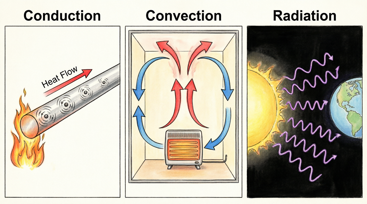
Text description of the Conduction, Convection, and Radiation image.
The image illustrates three methods of heat transfer: conduction, convection, and radiation, each represented within its own panel. The conduction panel on the left depicts a metal rod with visible heat flow represented by concentric circles and an arrow pointing from a flame on the left side of the rod. The middle panel shows convection within a box featuring a heater at the bottom. Arrows indicate a circular flow of red (warm) air rising and blue (cool) air descending. The right panel depicts radiation with the sun on the left emitting wavy lines towards Earth on the right, representing heat transfer through space.
The image below shows how heat can be lost in your home. Where do you think the majority of your energy losses occur?

Text description of the Heat Loss Examples image.
The image depicts a cutaway view of a two-story house, illustrating air flow patterns through various rooms. The house is divided into sections displaying different parts, including the bathroom, living area, and basement.
On the upper level, the bathroom is on the left, featuring a mirror above a sink, next to a toilet and a visible ventilation pipe. In the living area, there is a window and a door leading to a hallway, behind which is a chimney. The right section houses a laundry room with a washer and dryer, while a staircase leads to the basement.
The basement, situated below the main floor, contains a furnace and water heater. Arrows in various colors indicate air movement: red arrows show warm air rising, blue arrows show cool air descending, and purple arrows illustrate drafts or ventilation.
The structure has a gabled roof, and the exterior walls have visible masonry. The surrounding land includes a lawn.
9.3 Degree Days
9.3 Degree DaysWhat is a Degree Day?
Degree days are measures of how cold or warm a location is. Degree days compare the mean (the high temperature plus the low temperature divided by 2) outdoor temperature to a standard temperature; we use 65° Fahrenheit (F) in the United States.
How do you calculate a Degree Day?
The base temperature we use is 65°F. If the mean temperature is above 65°F, we subtract the base temperature (65°F) from the mean, and the result is Cooling Degree Days (CDD). If the mean temperature is below 65°F, we subtract the base temperature from the mean, and the result is Heating Degree Days (HDD).
A cooling degree day indicates a hot day and measures how much air conditioning we need to keep a building cool. A heating degree day indicates a cold day and measures how much heating we need to keep a building warm.
What do people use Degree Day data for?
Degree days are calculated for each day of the year, and we use the daily degree days to compare months and seasons. We often count CDDs and HDDs by census regions and divisions. Generally, people study degree-day patterns to assess the climate and the heating and cooling needs for different regions of the country. For example, the West North Central Census Division generally has the most HDDs, and the West South Central Census Division generally has the most CDDs each year.
Source: U.S. Energy Information Administration - Units and Calculators Explained
Heating Degree Days Examples
Example 1
Calculate the HDD for one day when the average outside temperature is 13°F.
Calculate the HDD for one day when the average outside temperature is 2°C.
Example 2
Given the following data, calculate the HDD for the week:
| Day | Average Temperature |
|---|---|
| Sunday | 49°F |
| Monday | 47°F |
| Tuesday | 51°F |
| Wednesday | 60°F |
| Thursday | 65°F |
| Friday | 67°F |
| Saturday | 58°F |
Heating Degree Day Example 2 Solution
For this problem, we need to calculate HDD for one full week. The data that is given for each day is the average outside temperature. For example, Sunday, the average outside temperature is 49°F. Monday it’s 47°F, Tuesday it’s 51°F, Wednesday it’s 60°F, Thursday it’s 65°F, Friday it’s 67°F, and on Saturday it’s 58°F.
| Day | Average Temperature (°F) |
|---|---|
| Sunday | 49 |
| Monday | 47 |
| Tuesday | 51 |
| Wednesday | 60 |
| Thursday | 65 |
| Friday | 67 |
| Saturday | 58 |
So we need to calculate heating degree days (HDD) for each day. To calculate heating degree days (HDD) for each day, we need to enter the Tbase value of 65 degrees for each day. HDD = Tbase minus the average outside temperature.
| Day | Average Temperature (°F) | Calculate HDD |
|---|---|---|
| Sunday | 49 | 1 day (65-49) |
| Monday | 47 | 1 day (65-47) |
| Tuesday | 51 | 1 day (65-51) |
| Wednesday | 60 | 1 day (65-60) |
| Thursday | 65 | 1 day (65-65) |
| Friday | 67 | 1 day (65-67) |
| Saturday | 58 | 1 day (65-58) |
Now you can calculate the HDD for each day. The HDD for Sunday is 65 degrees (the Tbase) minus 49 degrees (the outside temperature), which equals 16. Monday is 65-47=18, Tuesday is 65-51=14, Wednesday is 65-60=5, Thursday is 65-65=0, Friday is 65-67=0 (Remember when the average outside temperature exceeds 65, the heating degree days would be zero because you do not need to turn the heat on), and Saturday is 65-58=7.
| Day | Average Temperature (°F) | Calculate HDD |
|---|---|---|
| Sunday | 49 | 1 day (65-49)=16 |
| Monday | 47 | 1 day (65-47)=18 |
| Tuesday | 51 | 1 day (65-51)=14 |
| Wednesday | 60 | 1 day (65-60)=5 |
| Thursday | 65 | 1 day (65-65)=0 |
| Friday | 67 | 1 day (65-67)=0 |
| Saturday | 58 | 1 day (65-58)=7 |
Now you can add the degree days for the week.
| Day | Average Temperature (°F) | Calculate HDD |
|---|---|---|
| Sunday | 49 | 1 day (65-49)=16 |
| Monday | 47 | 1 day (65-47)=18 |
| Tuesday | 51 | 1 day (65-51)=14 |
| Wednesday | 60 | 1 day (65-60)=5 |
| Thursday | 65 | 1 day (65-65)=0 |
| Friday | 67 | 1 day (65-67)=0 |
| Saturday | 58 | 1 day (65-58)=7 |
| Total | 60 Degrees |
So the total sum for one full week is 60 degree days.
9.4 Seasonal Heating Degree Days
9.4 Seasonal Heating Degree DaysIn previous examples, we are assuming that the outside temperature remains the same for all 150 heating days in a season. This is not realistic, but it explains the method to calculate the HDD. In a more realistic example, we need to find the temperature difference for each day and add all the temperature differences.
We will now look at Seasonal Heating Degree Days (HDD), which is the sum of temperature differences of ALL days - rather than just 1 day or 1 week - during which heating is required.
The table below provides Seasonal HDDs for selected places in the United States. The higher HDD indicates a higher heat loss and, therefore, higher fuel requirements.
HDD is used to estimate the amount of energy required for residential space heating during a cool season, and the data are published in local newspapers or on the National Weather Service website.
| Place | Degree Days |
|---|---|
| Birmingham, AL | 2,823 |
| Anchorage, AK | 10,470 |
| Barrow, AK | 19,893 |
| Tucson, AZ | 1,578 |
| Miami, FL | 155 |
| Pittsburgh, PA | 5,829 |
| State College, PA | 6,345 |
Source: NOAA
Calculating Seasonal Heating Degree Days
To calculate Seasonal Heating Degree Days, use this formula:
Remember, in months where the average temperature is equal to or greater than 65, there will be no heating degree days, so the value for the month will be 0.
9.5 Insulation
9.5 InsulationWhy Insulation Matters
Keeping your home comfortable year-round starts with good insulation. Two of the simplest and most effective ways to save energy (and lower utility bills) are:
- Sealing air leaks around windows, doors, and ducts
- Adding or upgrading insulation in walls, attics, and floors
What Is Insulation?
Simply put, insulation is any material that slows down the flow of heat. It doesn't "create" warmth; instead, it acts like a thermal barrier that keeps heat inside during winter and outside during summer. A blanket doesn't actually create heat (unless it is an electric blanket), but it traps your body heat and keeping you warm. Your home insulation keeps the heat in your home from escaping.
Understanding R-Value: The Key Metric
Insulation is rated using something called an R-Value. The "R" stands for thermal resistance—how well a material resists heat flow.
The Golden Rule:
Higher R-Value = Better insulation
Lower R-Value = Poor insulation
(Note: R-Value is technically measured in units like ft²·°F·h/BTU, but you don't need to memorize the math. Just remember: the number tells you how well the material blocks heat.)
Real-World Example: Windows vs. Walls
- Single-pane window on a cold day: Feels freezing to the touch. Glass has a very low R-Value, so heat escapes easily.
- Interior wall: Feels much warmer. Behind the drywall, there's insulation (like fiberglass or foam) with a higher R-Value, which traps heat inside your living space.
How Layers Work Together
Insulation rarely works alone. In real homes, multiple materials combine to increase the overall R-Value. A typical exterior wall might include:
- Plywood sheathing
- Fiberglass or spray foam insulation
- Drywall
- Exterior siding or brick veneer
Each layer adds its own R-Value. When stacked together, they create a much stronger thermal barrier than any single material could provide on its own.
Look at the table below to learn about six types of insulation.
| Insulation | What is it made of? | What does it look like? | Additional Information |
|---|---|---|---|
Fiberglass
| Molten glass spun into microfibers | Pink or yellow in the form of batts or rolled blankets. | |
Rock Wool
| Basalt Rock (a volcanic stone) and recycled steel slag | Gray or brown fibers in batts or blankets or as shredded loose-fill. | Manufactured in a similar way as fiberglass, but with molten rock instead of glass. |
Cellulose
| Recycled paper – newsprint or cardboard shredded into small bits of fiber. | Blown in as loose fill. | It is treated with fire- and insect-resistant chemicals. |
Rigid Foam
| Different types, but some made from post-consumer recycled content from fast food containers and cups. | Rigid sheets that are applied directly to framing. | Best where space is limited, but a high R-value is needed. Can be installed on the interior of a wall, but if installed inside, must be covered by a fire resistant material like wallboard. One drawback to foam is it deteriorates unless it is protected from prolonged exposure to sunlight and water. It is also more expensive than other insulation. |
Synthetic Insulation
| Usually polystyrene or polyurethane foam. | Polystyrene comes as rigid boards, and Polyurethane comes as rigid boards or sprayed in place systems. | Polystyrene is used for insulating basements, cathedral ceilings, or sidewalls. Polyurethane foams are high performance insulating materials. |


Calculating the Composite R value of a wall, you would just add up all the R values of each layer.
Example
A ceiling is insulated with 0.75" plywood, 2" of polystyrene board, and a 3" layer of fiberglass. What is the R-Value for the ceiling?
Solution:
The ceiling consists of three layers, and all three layers together prevent the heat loss. So, we need to add the R-values of all three layers
¾" of plywood has an R-value of 0.94
2" of polystyrene at 5.0 per inch will have an R-value of 10.00
3" of fiberglass at 3.7 per inch will have an R-value of 11.10
So the R-value of the ceiling is 22.04 ft2 oF h / BTU.


Text description of the Wall Assembly R-Value Breakdown image.
The image illustrates a wall assembly with a focus on the R-Value breakdown, depicting different layers of wall construction and their respective R-Values against a blue background. On the left, a cross-section of a wall is shown with five distinct layers. From the exterior inward, these layers are: brick, wood siding, plywood sheathing, fiberglass insulation, vapor barrier, and drywall. To the right of the wall diagram, each layer is labeled with its material and corresponding R-Value contribution. The R-Values are: wood siding (+R-0.8), plywood sheathing (+R-0.5), fiberglass insulation (+R-11), vapor barrier (+R-0.5), and drywall (+R-0.5). Beneath these, the combined total R-Value is indicated as R-13. At the bottom, a red and orange gradient bar underscores the message: "Better Insulation = Higher R-Value."
9.6 Home Heating Fuels
9.6 Home Heating FuelsIn the United States, the fuel used to heat homes depends largely on location, climate, and available infrastructure.
Regional Patterns:
- Northeast: Cold winters mean high heating needs. Many homes use heating oil or natural gas.
- Midwest & Mountain States: Natural gas and propane are common; some rural areas still use wood or coal.
- South: Milder winters (fewer "heating degree days"—a measure of how cold it is over time) mean less heating overall. Electricity is the dominant heating source here.
- West Coast: Mix of natural gas and electricity, with growing interest in heat pumps and renewable energy.
Looking Ahead: Electricity is the second-most used heating fuel nationwide—and its use is expected to grow. Many states are promoting "electrification" (switching from gas/oil to electric systems) to reduce carbon emissions.

Text description of the Share of Homes by Primary Space Heating Fuel and Census Region image.
The image is a map of the United States divided into four Census regions: West, Midwest, South, and Northeast. Each region features a pie chart representing the primary space heating fuels used in 2009. The pie charts are color-coded according to a legend on the right, showing different fuels: natural gas (yellow), electricity (blue), heating oil (brown), propane (green), wood (light-brown), and kerosene/other (gray). In the West, the pie chart shows a majority in electricity with natural gas as a significant portion. The Midwest chart is dominated by natural gas. The South has a large section for electricity with natural gas also significant. The Northeast shows a mix of heating oil, natural gas, and electricity. The lower right corner has a separate pie chart indicating the U.S. total, summarizing 110 million heated homes, showing a predominant use of natural gas and electricity.
Fuel Comparisons
| Fuel | Capacity | Consumption | Additional Information |
|---|---|---|---|
| Natural Gas | Measured in British thermal units per hour (BTU/h). Most heating appliances for home use have heating capacities of between 40,000 and 150,000 BTU/h. In the past, gas furnaces were often rated only on heat input; today the heat output is given. | Consumption of natural gas is measured in cubic feet (ft3). This is the amount that the gas meter registers and the amount that the gas utility records when a reading is taken. One cubic foot of natural gas contains about 1,000 BTU of energy. | Utility companies often bill customers for CCF (100 cu. ft) or therms of gas used: one therm equals 100,000 BTUs. Some companies also use a unit of MCF, which is equal to 1,000 cu. ft. One MCF equals 1,000,000 BTUs (1 MM BTUs). |
| Propane or Liquefied Petroleum Gas (LPG) | Measured according to BTU/h. | Consumption of propane is usually measured in gallons; propane has an energy content of about 91.300 BTUs per gallon. | Can be used in many of the same types of equipment as natural gas. It is stored as a liquid in a tank at the house, so it can be used anywhere, even in areas where natural gas hookups are not available. |
| Fuel Oil | The heating (bonnet) capacity of oil heating appliances is the steady-state heat output of the furnace, measured in BTU/h. Typical oil-fired central heating appliances sold for home use today have heating capacities of between 56,000 and 150,000 BTU/h. | Oil use is generally billed by the gallon. One gallon of #2 fuel oil contains about 140,000 BTU of potential heat energy. | Several grades of fuel oil are produced by the petroleum industry, but only #2 fuel oil is commonly used for home heating. |
| Electricity | The heating capacity of electric systems is usually expressed in kilowatts (kW); 1 kW equals 1,000 W. A kilowatt-hour (kWh) is the amount of electrical energy supplied by 1 kW of power over a 1-hour period. Electric systems come in a wide range of capacities, generally from 10 kW to 50 kW. | Electricity is sold in kWh (kilowatts per hour). | The watt (W) is the basic unit of measurement of electric power. |
Heating Values of various fuels
Each unit of fuel when burned gives different amounts of energy. The energy that is released when a unit amount of fuel is burned is called the heating value. The heating value of a fuel is determined under a standard set of conditions. A comparison of approximate heating values of various fuels is shown in the table below.
| Fuel | Unit | Heating Value (BTU's) |
|---|---|---|
| Natural Gas | CCF (100 Cu. ft) or Therm | 100,000 |
| Natural Gas | MCF (1,000 Cu.ft) | 1,000,000 |
| Fuel Oil | Gallon | 140,000 |
| Electricity | kWh | 3,412 |
| Propane | Gallon | 91,300 |
| Bituminous Coal | Ton | 23,000,000 |
| Anthracite Coal | Ton | 26,000,000 |
| Hardwood | Cord | 24,000,000 |
Just as we saw back in Lesson 2, all energy conversion devices are not 100% effect. In most heating systems, we have some sort of furnace or boiler to burn our fuel. This process is not perfectly efficient.
Annual Fuel Utilization Efficiency (AFUE)
What Is AFUE?
AFUE (Annual Fuel Utilization Efficiency) is a rating that tells you how efficiently a furnace or boiler converts fuel into usable heat over an entire heating season.
Simple Definition:
AFUE = (Heat Output ÷ Fuel Input) × 100%
Think of it like a report card for your heating system—the higher the score, the better it performs!
How to Read AFUE Ratings
| AFUE Rating | What It Means | Example |
|---|---|---|
| 90% | 90% of fuel becomes heat; 10% is lost | For every $100 spent on fuel, $90 heats your home, $10 goes up the chimney |
| 80% | 80% efficient; 20% wasted | Older systems often fall in this range |
| 98% | Nearly all fuel is used for heating | Top-tier modern ENERGY STAR models |
What AFUE Does (and Doesn't) Measure
AFUE Measures:
- Efficiency of the furnace or boiler itself
- How well the unit converts fuel to heat at the source
- Performance under standardized testing conditions
AFUE Does NOT Measure:
- Heat loss through ductwork (leaky ducts can waste 20–30% of heated air)
- Poor insulation or air leaks in your home
- Thermostat settings or user behavior
- Distribution losses from pipes (in boiler systems)
Important: A 95% AFUE furnace can still heat your home inefficiently if your ducts are leaky or your attic isn't insulated!
9.7 Furnaces and Boilers
9.7 Furnaces and Boilers mxw1429.7.1 What Is a Furnace?
9.7.1 What Is a Furnace?A furnace is a heating system that warms air and distributes it throughout your home through a network of ducts and vents. It's the most common type of home heating system in the United States.

Text description of the Residential Furnace image.
The image features a furnace unit labeled "Lennox" positioned against a wall in a basement or utility area. The furnace consists of a gray metal body with a smooth texture and includes various components such as a large, curved duct that leads to the top of the unit. To the left, there is a metallic panel that holds a document with installation or operation guidelines, secured within a transparent holder. Below the furnace, there are several warning stickers and informational labels, including cautionary symbols related to safety. The surrounding environment appears to be unfinished concrete, with some visible piping and a glimpse of a red cooler in the background.
How Does a Furnace Work?
Most homes use gas furnaces. Here's the basic process:
- Ignition: Natural gas is lit in the burner
- Heat Exchange: The flames heat up a metal component called the heat exchanger
- Air Warming: Cool air from your home passes over the hot heat exchanger
- Distribution: A blower fan pushes the warmed air through ducts to rooms throughout your house
Energy Efficiency: What to Look For
When shopping for a furnace, energy efficiency saves money and reduces environmental impact. Here are three key features to understand:
AFUE Rating
AFUE (Annual Fuel Utilization Efficiency) measures how efficiently a furnace converts fuel into heat—similar to MPG for cars.
- Higher AFUE = Better efficiency
- Modern gas furnaces: 89–98% AFUE
- Example: A 90% AFUE furnace converts 90% of fuel into heat; 10% is lost
Heating Stages
Furnaces can have different operating modes:
| Type | How It Works | Energy Use |
|---|---|---|
| Single-stage | Runs at full power only | Less efficient |
| Two-stage | High or low power settings | More efficient |
| Variable-speed | Adjusts output continuously | Most efficient |
Think of it like a car: cruising at a steady (continuous) speed uses less gas than accelerating to full speed, coasting, and accelerating back to full speed.
ENERGY STAR Certification
ENERGY STAR is a government-backed label for energy-efficient products. Furnaces with this certification meet strict efficiency guidelines and can save you money on utility bills.
| Feature | Gas Furnace | Oil Furnace |
|---|---|---|
| Efficiency | 89–98% AFUE | 80–90% AFUE |
| Upfront Cost | Higher | Lower |
| Fuel Cost | Natural gas is cheaper | Heating oil is more expensive |
| Availability | Requires gas lines | Can be used anywhere (fuel delivered by truck) |
| Popularity | Most common today | Older homes, rural areas |
Bottom Line: Gas furnaces cost more upfront but save money long-term through better efficiency and lower fuel costs.
Furnace Maintenance Tips
A well-maintained furnace can last 15–20 years. Follow these basics:
Professional Installation: Most problems come from poor installation, not equipment failure
Annual Service: Have a technician inspect your furnace before each heating season
Filter Changes: Replace air filters every 1–3 months (dirty filters reduce efficiency and air quality)
Keep Vents Clear: Make sure air vents and the furnace area aren't blocked
9.7.2 What Is a Boiler?
9.7.2 What Is a Boiler?A boiler is a heating system that warms water (or creates steam) and circulates it through pipes to radiators or baseboard heaters throughout your home.

Text description of the Oil Heating Boiler image.
The image depicts an oil heating boiler system, illustrated in a diagrammatic format. At the center is a cylindrical combustion chamber filled with water, which exhibits a swirling pattern, indicating the flow of heated water. The water is color-coded, with the top half in shades of red representing hot water and the bottom half in shades of blue indicating cooler water. Below the combustion chamber, a flame is visible, symbolizing the burner mechanism that heats the water. Surrounding the boiler are several components labeled with clear text: an expansion tank is on the left, allowing for fluid expansion; a flue at the top releases smoke; a circulator pumps water; and heating pipes extend outward at the right, showing the flow of hot water into a heating system. Additional elements at the bottom include an oil tank, filter, fuel pump, and controls, alongside a thermostat for regulating temperature.
How It Works:
- Fuel (gas, oil, or electricity) heats water in a sealed tank
- Hot water or steam travels through pipes
- Radiators release heat into rooms
- Cooled water returns to the boiler to be reheated
| Feature | Furnace | Boiler |
|---|---|---|
| What It Heats | Air | Water/Steam |
| How Heat Moves | Through ducts and vents | Through pipes to radiators |
| Distribution | Forced air | Hydronic (water-based) |
| Also Provides | Can include air conditioning | Usually heating only |
Key Point: Both systems heat your home—they just use different methods to move heat energy around.
Repair or Replace? When to Make the Call
Heating systems typically last 15–20 years with proper care. Consider replacement if:
- Your furnace is over 10–15 years old
- AFUE rating is 80% or lower (modern units are 90%+)
- Frequent breakdowns or costly repairs
- Rising energy bills without increased usage
- Uneven heating throughout your home
- Unusual noises (banging, hissing, rattling)
- Visible rust, cracks, or leaks
Rule of Thumb: If repair costs exceed 50% of the price of a new system, replacement is usually the smarter investment.
9.8 Radiant Heating
9.8 Radiant HeatingBaseboard Radiators
In the baseboard hydronic heating systems (shown below), water is heated in a gas-fired or oil-fired furnace located in the basement. The heated water is distributed through pipes into baseboards in various rooms. The heat is then delivered through radiation and convection. Although these are called radiant heating systems, most of the heat delivered is by convection. Heat delivery into rooms or zones can be controlled by flaps or louvers.
Radiant Floor Heat

Text description of the Radiant Floor Heating image.
The image depicts a section of a modern interior space, focusing on a flooring installation. The foreground features wooden floorboards that have a light, natural finish. Underneath the wooden planks, bright red heating pipes can be seen, which are arranged in a looping pattern on a light gray tiled surface. The tiles have a grid-like design, enhancing the structural appearance of the floor beneath. In the background, large windows allow natural light to flood the room.
There are three types of radiant floor heat:
- Radiant air floors (air is the heat-carrying medium)
- Electric radiant floors
- Hot water (hydronic) radiant floors.
Types of Installation
Electric radiant floors
Electric radiant floors are usually only cost-effective if your electric utility company offers time-of-use rates. Time-of-use rates allow you to “charge” the concrete floor with heat during off-peak hours (approximately 9 p.m. to 6 a.m.). If the floor's thermal mass is large enough, the heat stored in it will keep the house comfortable for eight to ten hours without any further electrical input. This practice saves a considerable number of energy dollars compared to heating at peak electric rates during the day.
Hydronic systems
Hydronic (liquid) systems, popular and cost-effective systems for heating-dominated climates, have been in extensive use in Europe for decades.
Hydronic radiant floor systems pump heated water from a boiler through tubing laid in a pattern underneath the floor. The temperature in each room is controlled by regulating the flow of hot water through each tubing loop via a system of zoning valves or pumps and thermostats.
9.9 Heat Pumps
9.9 Heat PumpsUnder natural circumstances, heat only flows from high temperatures to low temperatures. In order to move heat from a low temperature environment to a high temperature environment, work needs to be done (or rather energy needs to be spent).
A device that moves the heat from a low temperature environment to a high temperature environment is called a heat mover. Recall Lesson 6 when we learned about refrigerators, this is the same principal.
An example of a heat mover is a heat pump. A heat pump is a heating/cooling system and also a forced-air system. Cooled (and sometimes humidified or electronically cleaned) air is usually delivered through the same ductwork and registers used by heated air.
A heat pump uses air-conditioning principles to extract heat from one place and deliver it to another, and vice versa. In addition to expelling heat from indoors, the system can be reversed to heat the home in the winter. Thus, a heat pump is a device that moves heat from a low-temperature to a high-temperature environment with the help of work that is put in.
Heat pumps are classified based on the low-temperature heat source:
- Air-source heat pump or Air-to-air heat pump.
Heat is transferred from the low-temperature air outside to the high-temperature interior. - Ground-source heat pump or Ground-to-air heat pump.
The earth is used as a heat sink in the summer and a heat source in the winter; the pump relies on the relative warmth of the earth for its heating and cooling production. - Water-source heat pump or Water-to-air heat pump.
Heat is transferred from low-temperature water outside (from a pond or a lake) to a high-temperature interior.
Efficiency of a Heat Pump
Efficiency of a heat pump is measured using a term Coefficient of Performance (COP), and it is the ratio of the useful heat that is pumped to a higher temperature, to a unit amount of work that is put in. We will look at COP in terms of air-source heat pumps.
A general expression for the efficiency of a heat engine can be written as:
Using the same logic that was used for heat engines, this expression becomes:
Where, Q Hot = Heat input at high temperature and Q cold= Heat rejected at low temperature. The expression can be rewritten as:
Note: Thot and Tcold must be expressed in the Kelvin Scale.
9.9.1 Air Source Heat Pumps
9.9.1 Air Source Heat PumpsAn air-source or air-to-air heat pump can provide both heating and cooling.
- In the winter, a heat pump extracts heat from outside air and delivers it indoors.
- On hot summer days, it works in reverse, extracting heat from room air and pumping it outdoors to cool the house.

Text description of the Heat Pump image.
The image is divided into two parts. On the left, there is a photograph of an outdoor heat pump unit positioned next to a brick wall, with greenery in the background. The unit is rectangular, featuring a large round fan in a mesh-covered front and is raised slightly above the ground on four black legs.
On the right side of the image, there is a diagram illustrating the refrigeration cycle of a heat pump system. The diagram shows a house with arrows indicating the flow of refrigerant between the outdoor and indoor components, with distinguishing features such as a compressor, fan, outdoor coils, and indoor coils. The components are depicted in a colorful manner, with blue and red lines indicating the flow of gas and liquid along with directional arrows.
Nearly all air-source and air-to-air heat pumps are powered by electricity. They have an outdoor compressor/ condenser unit that is connected with refrigerant-filled tubing to an indoor air handler. As the refrigerant moves through the tubing of the system, it completes a basic refrigeration cycle, warming or cooling the coils inside the air handler. The blower pulls in room air, circulates it across the coils, and pushes the air through ductwork back into rooms.
When extra heat is needed on particularly cold days, supplemental electric-resistance elements kick on inside the air handler to add warmth to the air that is passing through.
The Balance Point
As we have learned, air-source and air-to-air heat pumps work by extracting heat from the outside air. These heat pumps require a backup system to supplement their heating ability when the outdoor temperature gets below a certain temperature.
As the outdoor temperature drops, the heating requirement of the house increases and the output of the heat pump decreases. At some point, the temperature of the home’s heating requirement and the heat pump output match. This temperature is called the balance point and usually falls between 30-45 degrees Fahrenheit. For any temperatures below the balance point, supplemental heat will be required.
To locate the balance point, the heating requirement (BTUs/h) of the house and the heat pump output (BTUs/h) are plotted against the changes in outside temperature. The place where the home heating requirement and heat pump output lines cross is the balance point.
Take a look at the graph of the Balance Point.

Text description of the Balance Point Graph.
The image is a line graph depicting the relationship between temperature and heating requirements, heat pump output, and supplemental heat. The x-axis represents temperature in degrees Fahrenheit, ranging from 0 to 80. The y-axis represents BTUs per hour, ranging from 0 to 70,000. Three lines intersect on the graph:
- A brown dashed line labeled "Heat Pump Output" begins near the bottom right and slopes upwards to the left, indicating increasing BTU output as the temperature decreases.
- A green solid line labeled "Home Heating Requirement" starts at the top left and slopes downwards to the right, showing decreasing BTU requirements as the temperature increases.
- A green shaded area labeled "Supplemental Heat" fills the upper left portion between the green solid line and the y-axis.
The "Balance Point" is marked where the brown and green lines intersect, indicating where the heat pump output meets the home heating requirement.
9.9.2 Ground Source Heat Pumps
9.9.2 Ground Source Heat PumpsGround-source or geothermal heat pumps (GHPs) are similar to the air-source heat pumps, except that the source of heat is the ground instead of outdoor air.
Closed-Looped Systems
Horizontal
The horizontal type of installation is generally most cost-effective for residential installations, particularly for new construction where sufficient land is available. It requires trenches at least four feet deep.
Horizontal systems come in two types of layouts, the two pipes method and the slinky method.
Two Pipes
The most common horizontal layouts include:
Two Pipes Layout (Option 1) - One pipe buried at six feet, and another pipe buried at four feet.

Two Pipes Layout (Option 2) - Both pipes placed side-by-side at five feet in the ground in a two-foot wide trench.

The Slinky™ Method
The pipe is looped to allow more pipes in a shorter trench, which cuts down on installation costs and makes horizontal installation possible in areas not possible with conventional horizontal applications. Large commercial buildings and schools often use vertical systems because the land area required for horizontal loops would be prohibitive

Vertical
This type of system may be used when the soil is too shallow for trenching or when one does not want to disturb the existing landscaping.
For a vertical system, holes (approximately four inches in diameter) are drilled about 20 feet apart and 100 to 400 feet deep. Into these holes go two pipes that are connected at the bottom with a U-bend to form a loop. The vertical loops are connected with horizontal pipe (i.e., manifold), placed in trenches, and connected to the heat pump in the building

Benefits of GSHP
Click on the benefit listed below to find out more information.
9.9.3 Water Source Heat Pumps
9.9.3 Water Source Heat PumpsPond
If a home has source surface water, such as a pond or lake, this type of loop design may be the most economical, since there is no need to dig a trench or a well for the pipes in the ground. In this type of system, the fluid circulates through polyethylene piping in a body of water, just as it does in the ground loops. The pipe may be coiled in a slinky shape to fit more of it into a given amount of space. This loop is recommended only if the water level never drops below six to eight feet at its lowest level, to assure sufficient heat-transfer capability. Pond loops used in a closed system result in no adverse impacts on the aquatic system.

Open-Loop Systems
This type of system uses well(s) or surface body water as the heat exchange fluid that circulates directly through the GHP system. Once it has circulated through the system, the water returns to the ground through the well, a recharge well, or a surface discharge. This option is obviously practical only where there is an adequate supply of relatively clean water, and all local codes and regulations regarding groundwater discharge are met.

9.10 Solar Heating Systems
9.10 Solar Heating SystemsThe sun can be used as free source of heating, similar to what we saw in Lesson 7 on solar hot water systems. Active solar heating is quite rare, however many locations take advantage of passive solar heating in designing of homes.
Active Solar Heating
Active solar heating systems operate as follows:
- Flat plate collectors are usually placed on the roof or ground in the sunlight. The top or sunny side has a glass or plastic cover to let the solar energy in. The inside space is a black (absorbing) material to maximize the absorption of the solar energy.
- A fluid (water, glycol mixture or even air) is drawn from the storage tank by pump #1 and is pumped through the flat plate collector mounted on the roof of the house.
- The fluid absorbs the solar energy and is returned back to the tank.
- Warm water from the tank is pumped by pump #2 though the heating coil.
- The fan blows air (from the room) over the heated coil, and the heated air then passes into the room and heats the room.
- Cold air sinks to the bottom and is recirculated over the heating coil.
Note: The standby electric coil is automatically turned on and provides the heat when the water temperature to the heating coil drops because of consecutive cloudy days.
Passive Solar Heating

Text description of the Passive Solar Heating image.
The image illustrates a cross-section of a house designed for solar efficiency. The house features a sloped roof with solar water heat collectors positioned along the top, capturing sunlight from the sun. To the left, south-facing windows allow sunlight to enter the building, while insulated shades help manage heat. Beneath the windows, a thermal mass wall absorbs and retains heat. Inside, radiant heat thermal mass flooring is depicted, with arrows indicating heat distribution. A solar hot water storage tank is visible on the right side of the image. Two suns are included, one labeled “Summer High-Angle Sun” and the other “Winter Low-Angle Sun,” indicating the seasonal angle of sunlight exposure.
Passive systems do not use mechanical devices such as fans, blowers, or pumps to distribute solar heat from a collector. Instead, they take advantage of natural heat flow to distribute warmth. An example of a passive system for space heating is a sunspace or solar greenhouse.
Passive systems also make use of materials with large heat capacities (stone, water, or concrete) to store and deliver heat. These are called thermal masses.
Passive systems can be categorized into three types:
- Direct Gain - Allows the solar energy to come in through the south-facing window panes.
- Indirect Gain - Allows the solar radiation to heat a wall and then the energy is slowly delivered into the interior of the house. Openings in the wall (called a Trombe Wall), as shown in the figure below, promote convective currents:
- Cold room air enters the space between the glass panel and the wall through the bottom opening.
- As this cold air gets heated, it rises to the top and comes in through the top opening.
- Greenhouse Addition - An attached sunspace and/or solar greenhouse heated by the solar energy - where some of the energy is used to grow the plants and some of it is used to heat the interior of the house.
These systems are shown below.

Text description of the Addition Methods image.
The image is a diagram with three sections comparing different methods of solar gain in buildings. Each section is a simplified illustration of a house cross-section, showing how sunlight enters and affects the interior space.
The first section, labeled "Direct Gain," depicts sunlight entering directly through a window into a room. The house is drawn with a simple silhouette of a roof and walls, with a red arrow representing sunlight entering the room straight through the window.
The second section, labeled "Indirect Gain," shows sunlight hitting an interior thermal mass, such as a wall, which then radiates heat into the room. The illustration includes a red arrow pointing to the thermal mass, demonstrating the indirect flow of heat.
The third section, labeled "Greenhouse Addition," illustrates sunlight entering a greenhouse-like structure attached to the house before entering the main living space. This section includes two red arrows indicating sunlight entering the greenhouse and then proceeding into the building's interior
9.11 Operating Costs of Heating your Home
9.11 Operating Costs of Heating your HomeIt is clear now that when a unit of fuel is burned not all of it is available to the end user, and that as the furnace efficiency increases, higher amounts of heat will be available. An important question that needs to be addressed is how much it costs to buy the energy or heat to heat a place.
Fuel is usually sold in gallons or CCF or kWh. Comparing the actual cost of energy to produce a certain amount of heat for the end user would be easy if the comparison is made on an energy basis rather than on a unit basis. That is, \$/BTUs or ($/million BTU) rather than \$/gal or CCF or kWh.
Just a note: Industry uses MMBTU to mean Millions of BTU, this is just convention. MCF means 1000 Cubic Feet of Natural gas.
We can use the following formula to calculate Actual Energy Cost:
Energy Cost Examples
Example
Let’s say we need one million BTUs to keep a place warm at a certain temperature. What would it cost to get those million BTUs from oil or gas or electricity? Let’s assume that:
| Material | Cost per unit | Efficiency | Heating Value |
|---|---|---|---|
| Natural Gas | $3.20/MCF | 90% | 1,000,000 BTUs or 1.0 MM BTU/MCF |
| Oil | $5.53/Gallon | 85% | 140,000 BTUs or 0.14 MM BTUs/Gallon |
| Electricity | $0.1742/kWh | 97% | 3,412 BTUs or .003412 MM BTUs/kWh |
Note: The costs per unit vary widely by season and geopolitical factors
Using the formula below, we can calculate the Actual Energy Cost.
Energy Cost Example (with prices from 1995) (2:44)
Transcript: Energy Cost Example (2:44)
Onscreen Text:
Natural gas costs $9.74/MCF. Heating oil costs $0.99/gal. The natural gas furnace runs at 90% efficiency and the oil furnace runs at 80% efficiency. Which fuel is cheaper?
Presenter:
Ok. This 5.7 is an interesting problem here. We are trying to compare the prices of two fuels – Natural Gas which sells for $9.74/MCF, and we also have oil that sells at $0.99/gallon. We are trying to compare the prices of these two and choose which one is the best fuel or cheapest fuel. So we need to calculate the price per million BTUs so that we can compare these two fuels. And we also know the furnace efficiencies of each of these. Natural gas furnace efficiency is 0.9, and we know the oil furnace efficiency is 0.8; it is given. So we need to calculate the actual cost and compare the cost.
Natural gas actual cost will be cost per unit fuel, which is $9.74/MCF divided by the heating value per unit fuel. Heating value for this one happens to be 1.0 Million BTUs per MCF, and we have to multiply by the efficiency here in the denominator which is 0.9, so the Natural Gas price turns out to be $10.83 or $10.83 per Million BTUs (MMBTUs).
When you do similar calculation for oil here, the actual price is, per unit is $0.99 per gallon here and how many million BTUs do we get per gallon? 0.13 Million BTUs (0.13 MMBTUs). We have done this before. We have to have the same units here. Gallons and gallons and MCF and MCF here in this case (natural gas) and times the efficiency is 0.8. So the price works out to be $9.50 per Million BTUs. Same million BTUs would cost $10.82 for Natural Gas and oil would be $9.50, so oil is cheaper.
Payback Examples:
9.12 Conclusion
9.12 ConclusionCongratulations on completing this module on home heating and insulation. You've explored the science of heat transfer, calculated heating needs using degree days, compared fuels and systems, and learned how to evaluate energy upgrades. These aren't just classroom concepts—they're practical tools you can use for life.
Key Takeaways: What You Now Know
Heat moves in three ways:
Conduction (through solids), convection (through fluids), and radiation (through space). Understanding these helps you identify where homes lose heat—and how to stop it.
Heating Degree Days (HDD) quantify climate demand:
The formula (65°F – Average Temp) × Days lets you compare heating needs anywhere. More HDD = more energy required.
Insulation slows heat loss:
R-Value measures thermal resistance. Higher R-Value = better performance. Layers of materials work together to create stronger thermal barriers.
Fuel choice affects cost and comfort:
Natural gas, oil, propane, and electricity each have pros and cons. Efficiency ratings (AFUE for furnaces, COP for heat pumps) tell you how much fuel actually becomes usable heat.
Payback analysis guides smart decisions:
The formula Additional Cost ÷ Annual Savings = Payback Period helps you decide if an upgrade is worth the investment.
Systems matter:
Furnaces heat air, boilers heat water, heat pumps move heat, and solar captures free energy. Each has a role depending on climate, budget, and goals.
Connect to Your World
The next time you need to replace your heating system, you’ll be equipped to make smart, informed choices.
- "Check your local Heating Degree Days first—your climate determines your heating needs."
- "Seal air leaks and upgrade insulation before replacing your furnace—it's often cheaper and just as effective."
- "Compare fuels using cost per useful BTU, not just price per gallon or therm."
- "Look for ENERGY STAR models and calculate payback—not just upfront cost."
- "In mild climates, a heat pump can heat AND cool efficiently. In very cold areas, a high-efficiency gas furnace may be better."